
Dereverberation system and dereverberation method

a dereverberation system and dereverberation technology, applied in the direction of electrical transducers, instruments, sound producing devices, etc., can solve the problem of difficulty in semi-blind mint processing methods, and achieve the effect of reducing calculation amount and calculation tim

Active Publication Date: 2010-03-04
HONDA MOTOR CO LTD
View PDF0 Cites 2 Cited by
  • Summary
  • Abstract
  • Description
  • Claims
  • Application Information

AI Technical Summary

Benefits of technology

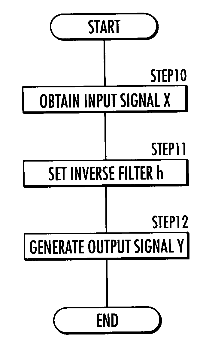
[0009]According to the dereverberation system and the dereverberation method of the present invention, the inverse filter is set by using the pseudo-inverse matrix of a non-square matrix as the correlation matrix of the input signals. According thereto, the microphone numbers, the filter numbers and the filter length Nh can be arbitrarily selected without the need to satisfy conditions for obtaining the rigorous inverse matrix, respectively. Thereby, the inverse filter can be used to generate She output signals in an arbitrary condition where the microphone numbers are restrained, the filter length is restrained in consideration of the signal processing performance of the system, or the like. As a result thereof, the dereverberation system and the method can cope with an arbitrary condition flexibly and will be capable of recognizing a sound or a sound source signal.
[0013]According to the dereverberation system of the present invention, it is expected to reduce calculation amount and calculation time needed to set the inverse filter by following the approximation method based on the presumption that the mentioned condition is satisfied.

Problems solved by technology

Thereby, it is difficult for the semi-blind MINT method to perform the processing adaptively in a high speed.

Method used


Image

  • Dereverberation system and dereverberation method
  • Dereverberation system and dereverberation method
  • Dereverberation system and dereverberation method

Examples


first embodiment

DIF: Decorrelation based Inverse Filter

[0054](Single Input / Output System) h(t) is obtained by excluding delay of the transfer system and assuming g(0)≠0 only. The relational expression (017) and rxy(0)=g(0) are expressed by the relational expression (111) rising an input signal vector (used for calculating the Correlation value) XL(t), an output y(t), a desired vector d of the correlation value, and an expectation value E[˜].

E[xL(t)y(t)]=d

xL(t)=[x(t)x(t−1) . . . x(t−L+1)]  T

d=[g(0)0 . . . 0]T  (111)

[0055]Herein, L=Ng+Nh−1. “T” denotes transposition.

[0056]The output y(t) is expressed by the relational expression (112) using an input signal vector (for the filter) xh(t) and a filter coefficient vector h.

y(t)=xhT(t)h

xh(t)=[x(t)x(t−1) . . . x(t−Nh+1)]T

h=[h(0)h(1) . . . h(Nh−1)]T  (112)

[0057]Therefore, the relational expression (111) can be transformed to the equation (113).

Ph=d

R=E [xL(t)xhT(t)]  (113)

[0058]Herein, R is a non-square correlation matrix of inputs of L rows by Nh columns...

second embodiment

DAIF: Decorrelation based Adaptive Inverse Filtering

[0065](Single Input / Output System)

[0066]An inverse filtering is performed adaptively by using the correlation values of the input and output signals. In order to obtain adaptively the solution to the relational expression (111), an error cost J(h) expressed by the relational expression (211) is defined.

J(h)=∥e∥2+σ∥h∥2

e=d−Rh  (211)

[0067]Herein, “σ” is a weight to the norm of the solution. When the weight σ becomes greater, the variation of the transfer function or the robustness to noises is improved; however, the control accuracy degrades. h which makes minimum the error cost J(h) is obtained according to the gradient method by the relational expressions (212) and (213).

h=h−μJ′(h)  (212)

J′(h)=−RT(d−Rh)+σh  (213)

[0068]Herein, “μ” is a step-size parameter. The step-size parameter μ may be a constant or may be adjusted adaptively. As an adaptive adjusting method for the step-size parameter μ, the Newton method, for example, may be ad...

third embodiment

R-DAIF: Real time Decorrelation based Adaptive Inverse Filtering

[0072](Single Input / Output System)

[0073]R-DAIF is expressed by the relational expression (316) transformed from the relational expression (216) under the assumption that the following two conditions are satisfied.

J′(t)=−R̂T(t)(d−R(t)h(t))+σh  (316)

[0074](A First Condition)

[0075]The filter h(t) varies slower than the estimated correlation matrix R̂(t), and the approximation formula (302) is valid.

Ew[xL(t)xh(t)]h(t)≈Ew[xL(t)y(t)]  (301)

[0076](A Second Condition)

[0077]The non-stationary components of the estimated correlation matrix R̂(t) are less than the stationary components thereof, and the approximation formula (302) is valid.

RT(t)R̂(t)≈Ew[xn(t)xLT(t)xL(t)xnT(t)]  (302)

[0078](Multiple Input / Output System)

[0079]R-DAIF in a multiple input / output system is calculated according to the relational expression (326).

J′(t)=−G(0)Ew[xNh(t)xT(t)]+Ew[pN(t)xNh(t)yT(t)+]σHh(t) PN(t)=∥xNL(t)∥2  (326)

[0080]In the multiple input / output...


PUM


Abstract

Provided is a dereverberation system or the like which copes with an arbitrary condition flexibly and is capable of recognizing a sound or a sound source signal. According to the dereverberation system, an inverse filter (h) is set by using a pseudo-inverse matrix (R+) of a non-square matrix (R) as a correlation matrix of input signals (x). On the basis of the inverse filter (h) and an estimated correlation matrix (R̂) generated according to a window function (w), an error cost (J(h) between a correlation value of the input signals (x) and output signals (y) and a desired correlation value (d) is calculated. On the basis of the error cost (J(h)), the inverse filter (h) is adaptively updated according to a gradient method.

Description

BACKGROUND OF THE INVENTION[0001]1. Field of the Invention[0002]The present invention relates to a dereverberation system and a dereverberation method.[0003]2. Description of the Related Art[0004]There has been proposed a semi-blind MINT method extended blindly from a MINT method fulfilling a rigorous inverse filter (refer to: K. Furuya and A. Kataoka, “Robust speech dereverberation using multichannel blind deconvolution with spectral subtraction”, IEEE Trans. on Speech and Audio Processing, vol. 15, no. 5, pp. 1579-1591, 2007). The validity thereof has been reported as an application in dereverberation for a remote meeting system.[0005]However, the semi-blind MINT method is configured to design the inverse filter after information of a transfer system has been estimated blindly in 2 steps. Accordingly, it is needed to update the information of the transfer system and the inverse filter in a defined constant time frame in order to perform the processing adaptively. Thereby, it is di...

Claims


Application Information

Patent Timeline
IPC IPC(8): H04B3/20
CPCH04S1/002
Inventor NAKAJIMA, HIROFUMINAKADAI, KAZUHIROHASEGAWA, YUJITSUJINO, HIROSHI
Owner HONDA MOTOR CO LTD
Learn More