Fuel cell systems with water recovery from fuel cell effluent

a fuel cell and effluent technology, applied in the direction of fuel cells, fuel cell control, regenerative fuel cells, etc., can solve the problems of not allowing efficient condensation of water, too much water in the fluid stream for fuel cell system reuse, and difficult to achieve water efficient condensation

Inactive Publication Date: 2010-03-04
IDATECH LLC
View PDF74 Cites 27 Cited by
  • Summary
  • Abstract
  • Description
  • Claims
  • Application Information

AI Technical Summary

Problems solved by technology

Efficient recovery of the water in a fuel cell system may be problematic.
As a result, the water in the fluid stream may be too dilute for reuse in the fuel cell system as water vapor.
The relatively low humidity of the fluid stream (and relatively low dewpoint) thus may not permit efficient condensation of water from the fluid stream for water recovery in liquid form at, or near, ambient temperatures.
Moreover, water recovery by cooling the fluid stream via heat exchange with the ambient environment may be unreliable due to diurnal, seasonal, and geographical variations in the ambient temperature.
However, the active cooling mechanism may add substantial complexity and cost to the fuel cell system, and / or operation of the active cooling mechanism may consume significant energy, thereby reducing the overall energy efficiency of the fuel cell system.

Method used


Image

  • Fuel cell systems with water recovery from fuel cell effluent
  • Fuel cell systems with water recovery from fuel cell effluent
  • Fuel cell systems with water recovery from fuel cell effluent

Examples


Embodiment Construction

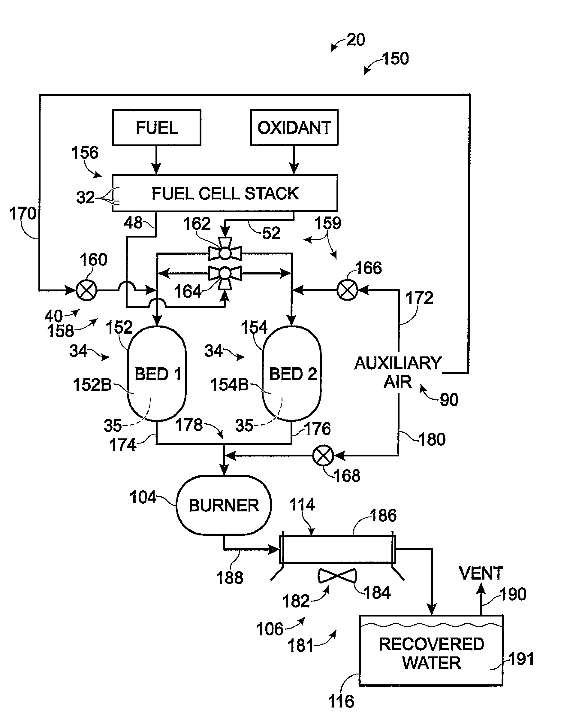
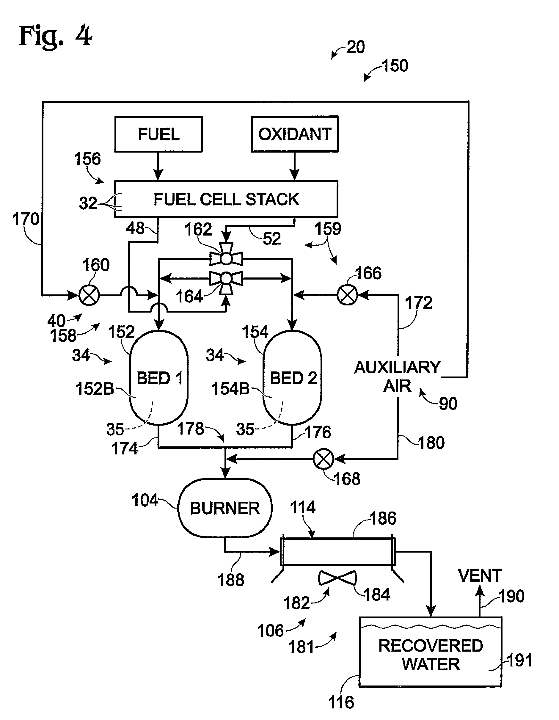
[0019]The present disclosure is directed to fuel cell systems, including associated methods and apparatus, that use a desiccant to recover water from fuel cell effluent. A fuel cell system according to the present disclosure may include one or more fuel cells configured to generate electrical output from electrochemical reaction of a supplied fuel and a supplied oxidant while emitting effluent. The effluent may include an anode exhaust, which may provide an exhausted fuel, and a cathode exhaust, which may provide an exhausted oxidant. The fuel cell system also may include a desiccant (i.e., a drying agent) that is disposed downstream of the fuel cells, such as part of one or more dryers, and configured to receive at least a portion of the effluent, such as at least a portion of the anode exhaust, cathode exhaust, or both. The desiccant may bind water from at least a portion of the effluent, such as by adsorption, absorption, or both. Moreover, the desiccant may bind water from one o...


PUM

PropertyMeasurementUnit
voltageaaaaaaaaaa
electricalaaaaaaaaaa
heataaaaaaaaaa

Abstract

Fuel cell systems that use a desiccant to recover water from fuel cell effluent. In some embodiments, the fuel cell system may include one or more fuel cells configured to generate electrical output from a supplied fuel and an oxidant while emitting effluent. The fuel cell system also may include a desiccant disposed downstream of the one or more fuel cells. The desiccant may bind water from at least a portion of the effluent. Heat then may be generated to release bound water from the desiccant. The heat may be generated by combustion of an exhausted fuel from the fuel cells and / or by combustion catalyzed by a combustion catalyst disposed downstream of the fuel cells.

Description

GOVERNMENT LICENSE RIGHTS[0001]This invention was made with Government support under W909MY-06-C-0028 awarded by the Department of the Army. The Government has certain license rights in the invention.FIELD OF THE DISCLOSURE[0002]The present disclosure is directed generally to fuel cell systems, and more particularly to fuel cell systems that use a desiccant to recover water from fuel cell effluent.BACKGROUND OF THE DISCLOSURE[0003]Fuel cell stacks are electrochemical devices that produce water and an electrical potential from a fuel, such as a proton source, and an oxidant. Many conventional fuel cell stacks utilize hydrogen gas as the proton source and oxygen gas, air, or oxygen-enriched air as the oxidant. Fuel cell stacks typically include many fuels cells that are fluidly and electrically coupled together between common end plates. Each fuel cell includes an anode region and a cathode region that are separated by an electrolytic barrier. In some fuel cells, the electrolytic barr...

Claims


Application Information

Patent Timeline
Patent Type & Authority Applications(United States)
IPC IPC(8): H01M8/00H01M8/18
CPCH01M8/04022Y02E60/50H01M8/04171H01M8/0432H01M8/04328H01M8/04335H01M8/04343H01M8/0435H01M8/04365H01M8/045H01M8/04507H01M8/04514H01M8/04522H01M8/04559H01M8/04589H01M8/04649H01M8/04164
Inventor RENN, CURTISS
Owner IDATECH LLC
Why Eureka
Try Eureka