

Laparoscopic instrument and related surgical method
- Summary
- Abstract
- Description
- Claims
- Application Information
AI Technical Summary
Benefits of technology
Problems solved by technology
Method used
Image

Examples
Embodiment Construction
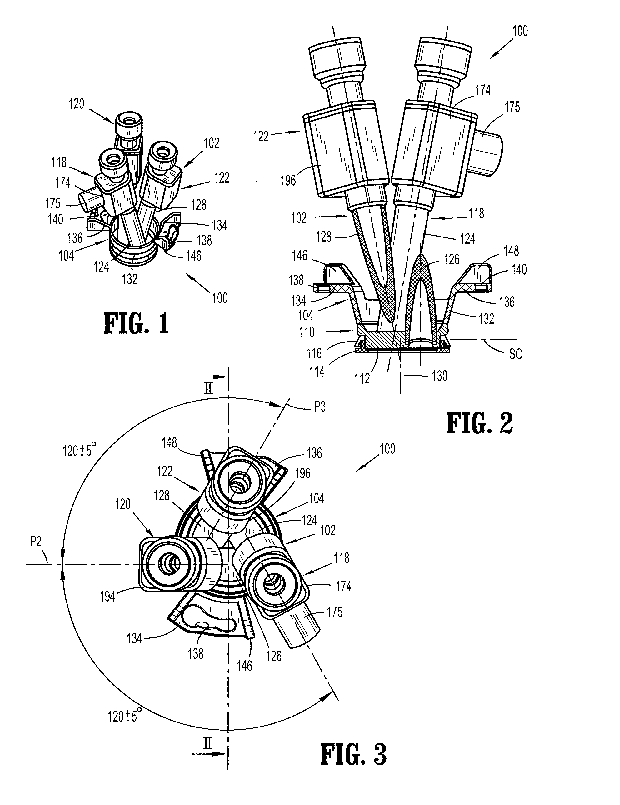
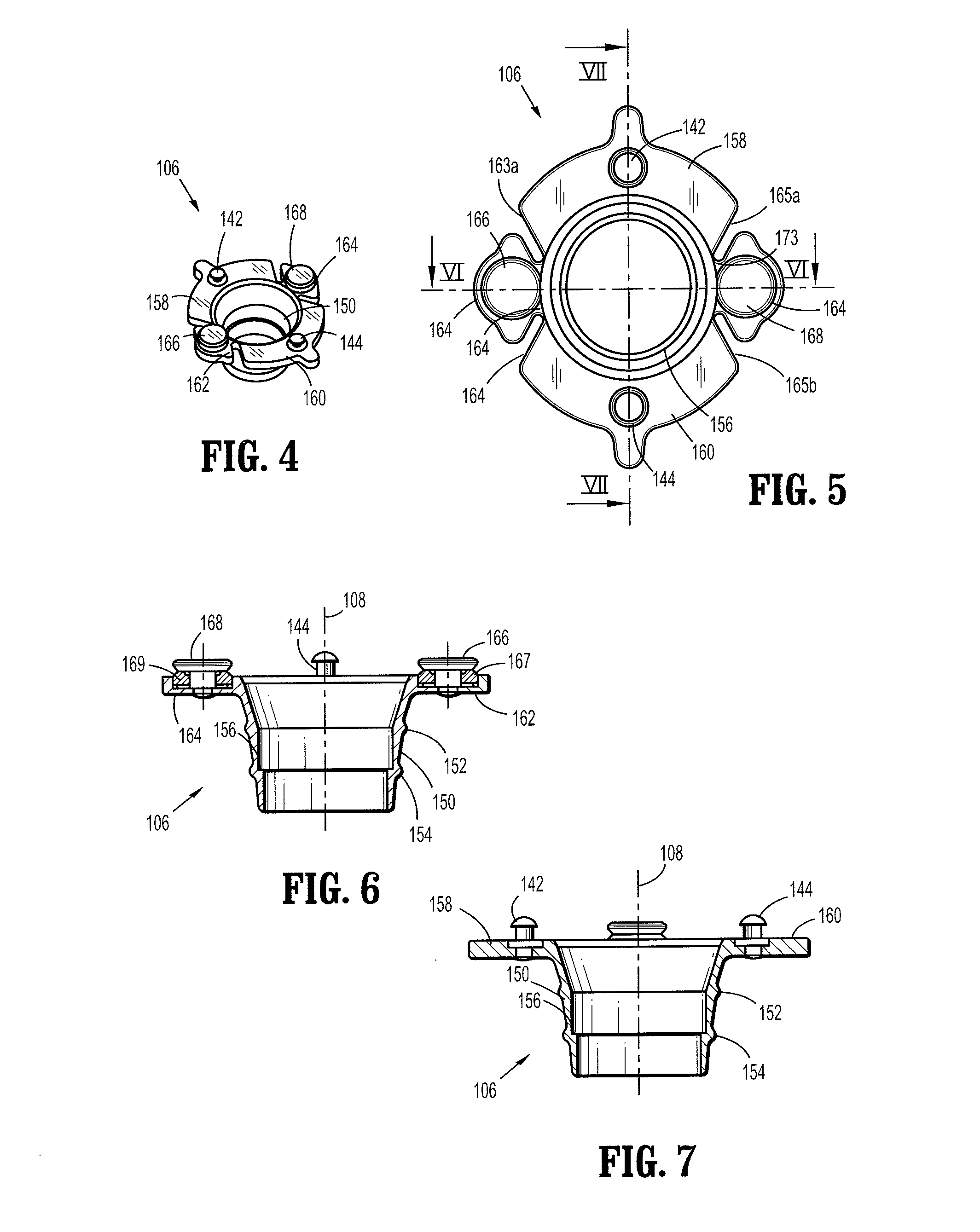
[0087]As depicted in FIGS. 1-3, a laparoscopic port or cannula assembly 100 comprises a cannula unit 102 and a connector 104 associated therewith for removably fastening the cannula unit to an annular port holder 106 (FIGS. 4-8 and 10) that is disposed in an opening (e.g., formed in the umbilicus) in a patient. Cannula unit 102 is coupled to port holder 106 by connector 104 so as to permit rotation of cannula unit 102 about a longitudinal axis 108 (FIGS. 7 and 10) of holder 106.
[0088]Cannula unit 102 comprises a base or frame 110 that is insertable into and removably attachable to port holder 106. Base or frame 110 includes a planar panel or wall 112 defining a closure surface or plane SC extending, during a laparoscopic surgical procedure, substantially tangentially to the patient's skin at the opening through with port holder 106 extends. Base or frame 110 further includes a seating ring 114 and a sealing ring 116.
[0089]Cannula unit 102 additionally comprises three cannula members...
PUM
 Abstract
Description
Claims
Application Information