Supercharge Your Innovation With Domain-Expert AI Agents!

Automatic transmission system and hydraulic control device and method thereof

a transmission system and hydraulic control technology, applied in mechanical equipment, gearing details, instruments, etc., can solve the problems of increased system size, parts count and manufacturing cost, and substantial changes in the design of the valve body, and achieve the opening/closing condition of the cooler bypass valv

Inactive Publication Date: 2010-03-04
JATCO LTD +1
View PDF5 Cites 4 Cited by
  • Summary
  • Abstract
  • Description
  • Claims
  • Application Information

AI Technical Summary

Benefits of technology

The present invention provides an automatic transmission system that allows lubricating oil to bypass a transmission oil cooler under optimal conditions without increases in system size and parts count and substantial changes in equipment design. The system includes a hydraulic control device and method that controls the valve actuator to actuate the switching valve, which switches hydraulic fluid to the hydraulic actuators. The control unit judges whether the transmission is in a low lubrication state and controls the valve actuator to switch the switching valve to the bypass position, allowing the hydraulic fluid to flow directly to the lubrication-requiring portions. The invention also includes a parameter detection unit that detects a given parameter of the transmission, such as shift range or oil temperature, and a control unit that judges the lubrication state of the transmission based on the detected parameter and controls the switching valve accordingly. The hydraulic control device and method provide an efficient solution for cooling lubricating oil in an automatic transmission system.

Problems solved by technology

There thus arise problems such as increases in system size, parts count and manufacturing cost and substantial changes in valve body design.
In this case, however, the opening / closing condition of the cooler bypass valve depends on the hardware specifications of the valve body and may not be set optimally due to low flexibility in bypass opening.

Method used


Image

  • Automatic transmission system and hydraulic control device and method thereof
  • Automatic transmission system and hydraulic control device and method thereof
  • Automatic transmission system and hydraulic control device and method thereof

Examples


Embodiment Construction

[0019]The present invention will be described in detail below with reference to the drawings.

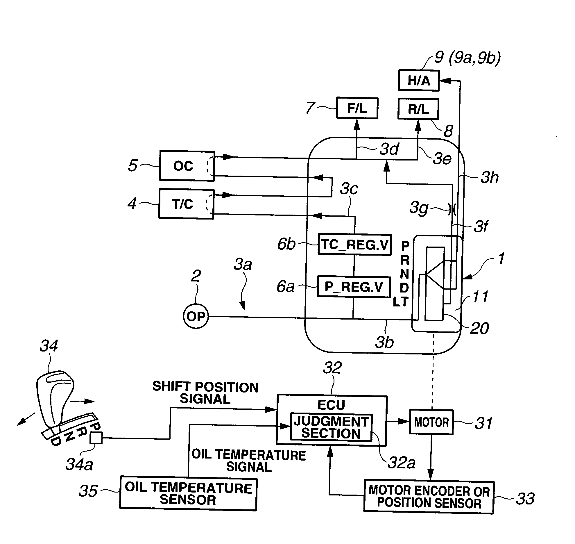
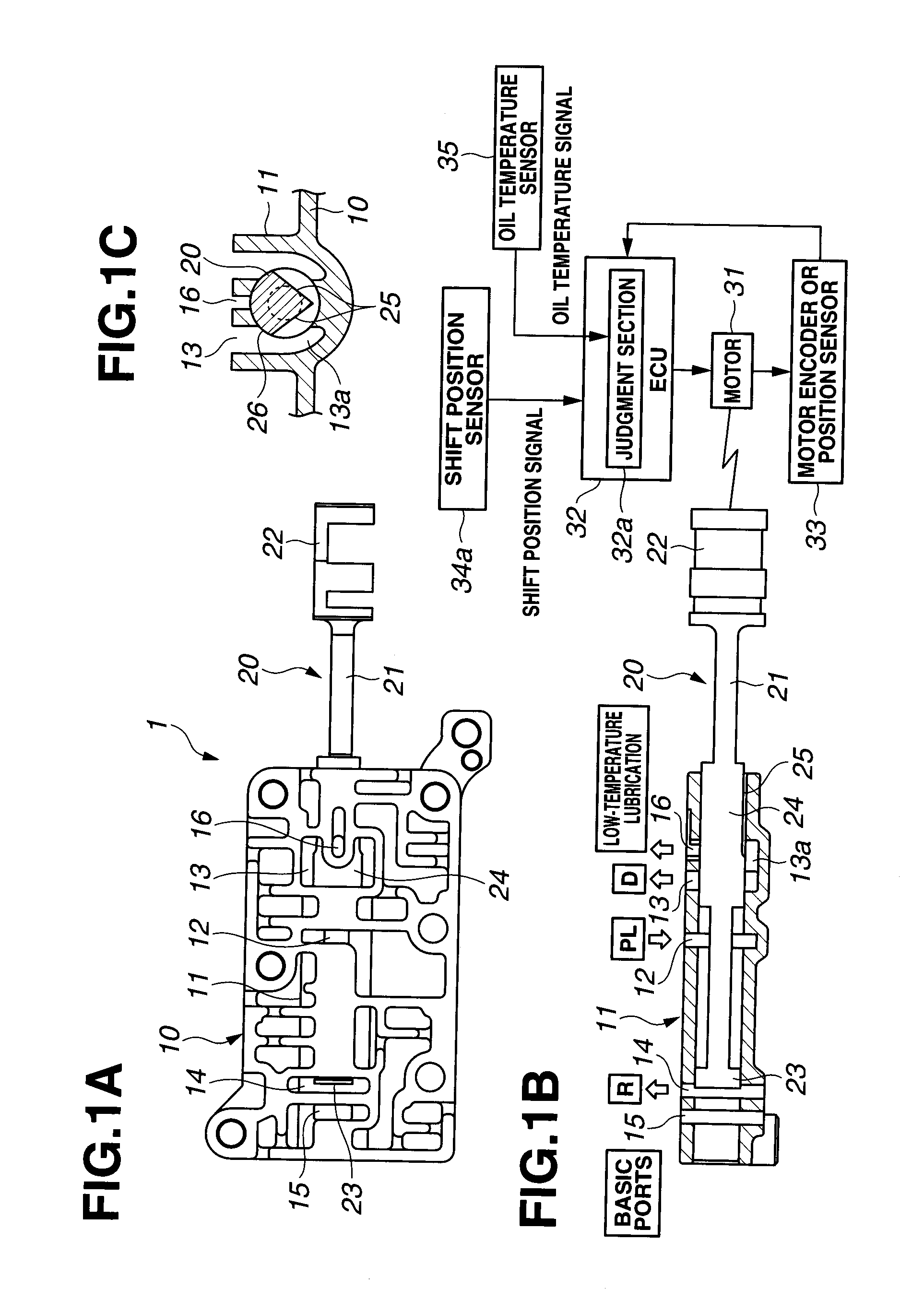
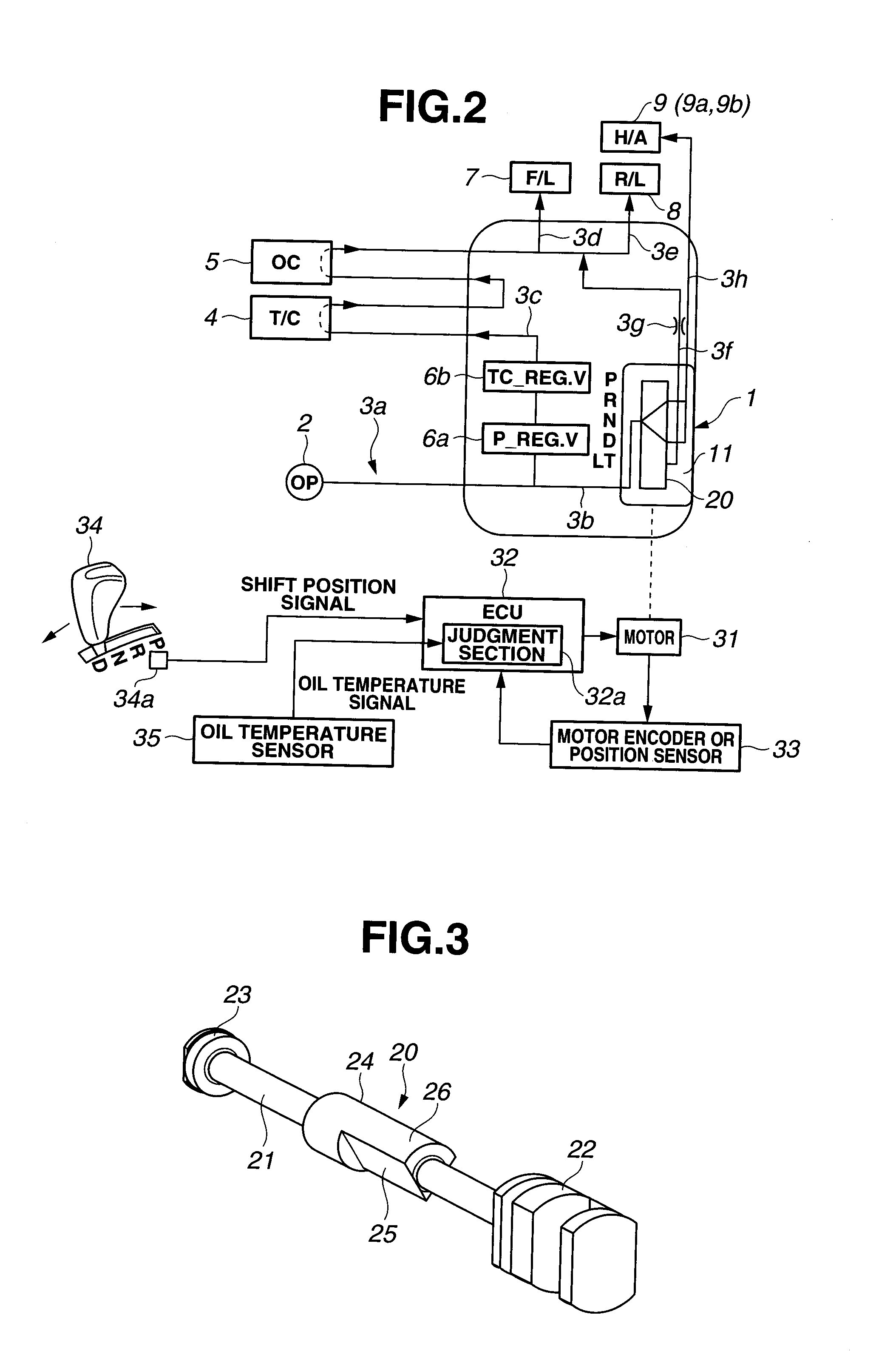
[0020]Referring to FIG. 2, an automatic transmission system of an automotive vehicle according to one embodiment of the present invention includes a transmission in which a plurality of transmission elements have sliding portions 7 and 8 and hydraulic actuators 9 (e.g. hydraulic chambers) to actuate the transmission elements and thereby establish a power transmission path from an engine to drive wheels according to a position of a shift lever 34, i.e., a shift range of the transmission selected by a vehicle driver. Herein, the transmission has a plurality of shift ranges such as P range (parking range), N range (neutral range), D range (forward drive range) including a first speed, a second speed and other forward drive speeds and R range (reverse drive range). The shift lever 34 has a plurality of operating positions such as P-range position, N-range position, D-range position and R-range p...


PUM


Abstract

An automatic transmission system includes a transmission having transmission elements with lubrication-requiring portions and hydraulic actuators therefor, a switching valve that supplies hydraulic fluid to the hydraulic actuators, a valve actuator that actuates the switching valve, a shift range detection unit that detects a selected shift range of the transmission, and a control unit that controls the valve actuator to actuate the switching valve in accordance with the selected transmission shift range. The switching valve has a bypass position to provide a supply of the hydraulic fluid to the lubrication-requiring portions by bypassing a transmission oil cooler. The control unit judges whether the transmission is in a low lubrication state based on a given operating parameter of the transmission and controls the valve actuator to switch the switching valve to the bypass position at the time the transmission is judged as being in the low lubrication state.

Description

BACKGROUND OF THE INVENTION[0001]The present invention relates to an automatic transmission system of an automotive vehicle etc. having an oil cooler to cool transmission oil. The present invention also relates to a hydraulic control device and method for an automatic transmission.[0002]Japanese Laid-Open Patent Publication No. 2007-64268 disclose one type of automatic transmission system, which includes a transmission having a plurality of transmission elements such as gear trains, multiple disc clutches / brakes, belt drives etc. and a hydraulic control device having a manual valve, a valve actuator such as a motor, a shift position sensor and a control unit that controls the valve actuator to actuate the manual valve such that the manual valve switches a supply of hydraulic fluid to hydraulic actuators of the transmission elements based on a detection signal from the shift position sensor. This configuration makes it possible to secure assured shift control of the transmission acco...

Claims


Application Information

Patent Timeline
Patent Type & Authority Applications(United States)
IPC IPC(8): G06F19/00F16H59/72F16H61/00F16H61/02F16H61/28
CPCF16H57/0434Y10T477/6931F16H61/0286F16H59/72
Inventor YAMAMOTO, HIDEHARUKAIZU, KENICHIISHI, HIDEKINEBASHI, TOSHIOMINAGASHIMA, FUMITAKAOOSHIRO, RYUSUKE
Owner JATCO LTD
Features
  • R&D
  • Intellectual Property
  • Life Sciences
  • Materials
  • Tech Scout
  • Unparalleled Data Quality
  • Higher Quality Content
  • 60% Fewer Hallucinations
Learn More