System and method for stochastically predicting the future states of a vehicle

a future state and stochastic prediction technology, applied in the field of methods and systems for predicting the future state of vehicles, can solve problems such as the problem of using ni alone to predict the future path of vehicles, and achieve the effect of more accurate predictions and computationally faster

Inactive Publication Date: 2010-03-04
TOYOTA MOTOR CO LTD
View PDF2 Cites 57 Cited by
  • Summary
  • Abstract
  • Description
  • Claims
  • Application Information

AI Technical Summary

Benefits of technology

[0012]Thus, it is an object of the present invention to use UT and NI together to stochastically predict the future states of the vehicle (e.g., the vehicle's position, orientation, velocity, yaw-rate, and acceleration). This invention allows for the prediction routine to maintain nonlinear models and, consequently, provide more accurate predictions. That the mean of the prediction obtained using UT and NI together was more accurate than obtained by NI alone was unexpected. Furthermore, the invention has been shown to be computationally faster than prior prediction methods.

Problems solved by technology

The inventors discovered that using NI alone to predict the future path of a vehicle is problematic because the non-linear models of vehicular dynamics are not perfect and sensor measurements are noisy.
UT accounts for the uncertainty of the model and noisy sensor measurements.

Method used


Image

  • System and method for stochastically predicting the future states of a vehicle
  • System and method for stochastically predicting the future states of a vehicle
  • System and method for stochastically predicting the future states of a vehicle

Examples


Embodiment Construction

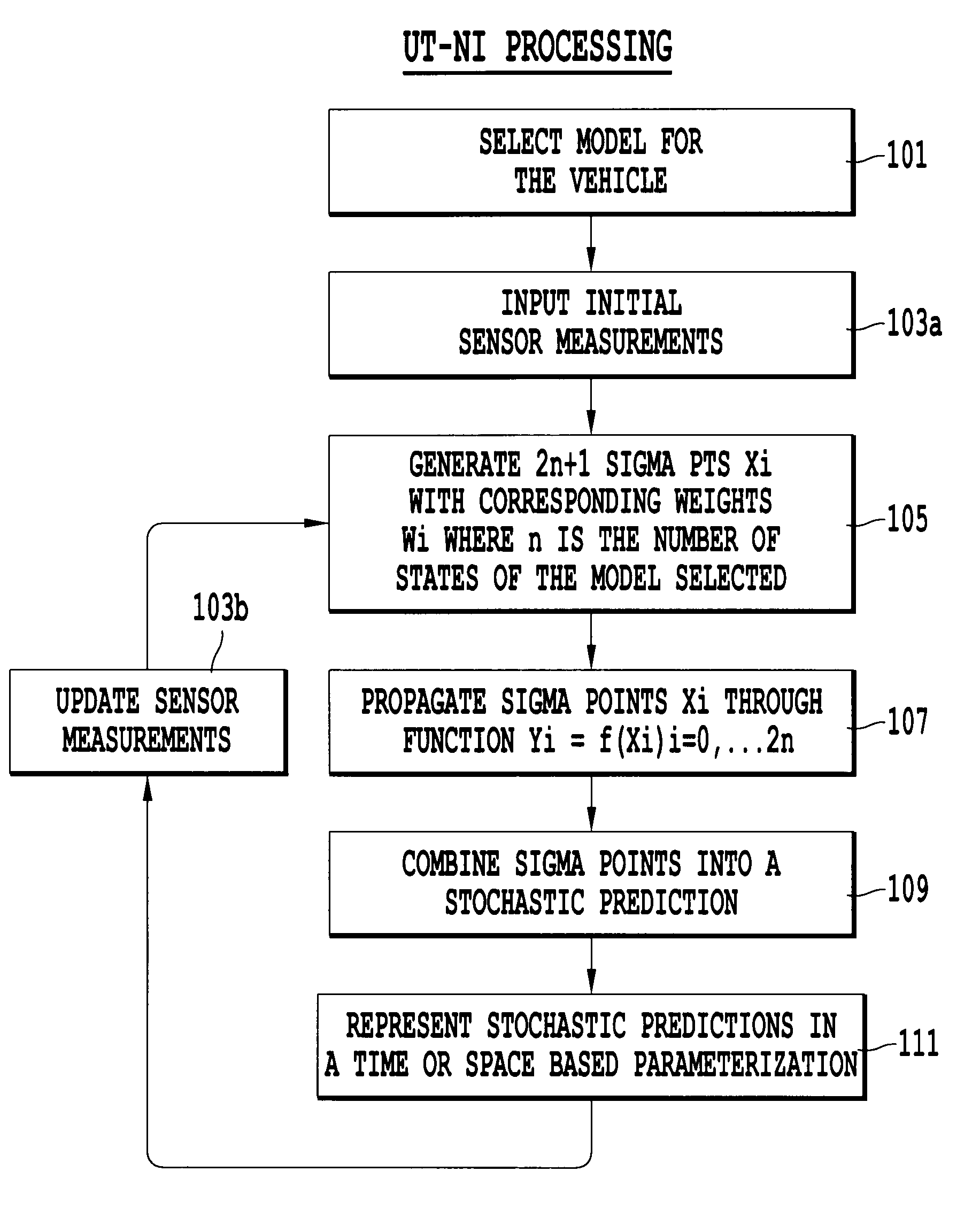
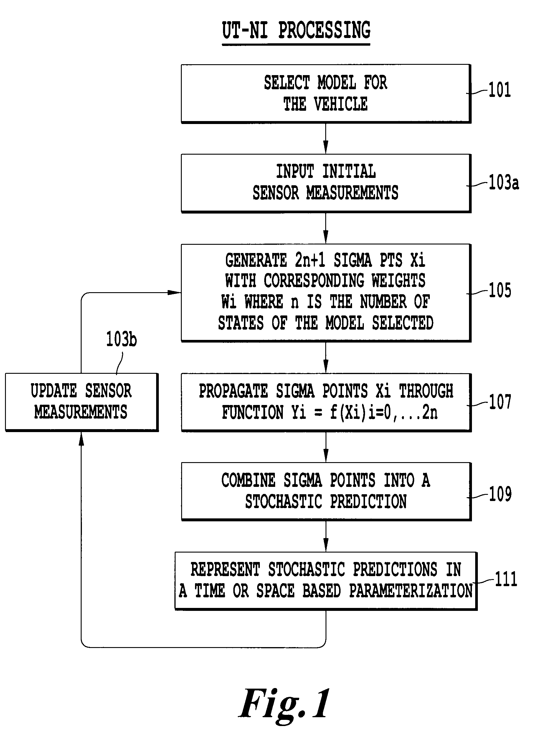
[0029]Referring now to the drawings, wherein like reference numerals designate identical or corresponding parts throughout the several views. FIG. 1 is a flow chart illustrating the processing steps for predicting the future states of a vehicle. Description herein will be directed to an automobile. However, this invention is applicable to other moving objects which are suitable for non-linear modeling.

[0030]In step 101, a non-linear model for the vehicle is chosen. Many vehicle-level models exist. The transformation between the vehicle coordinate frame and the earth coordinate frame implies that all models will at least include some trigonometric nonlinearities. Any model that involves yaw and lateral motion of the vehicle will introduce further nonlinear behavior.

[0031]The model described herein is the CB model. However, other dynamic models which can be utilized include the CA, KU, and KB models. Each model consists of differential equations which, when solved, represent the dynam...


PUM


Abstract

A method for predicting future states of a vehicle including the steps of selecting a model having n states reflecting dynamic features of the vehicle; inputting noisy sensor measurements representing a current state of the vehicle to generate (2n+1) sigma points Xi where i=0, . . . . 2n, each of the sigma points having n states; performing (2n+1) integrations, each integration includes propagating the n-states of the respective sigma points Xi through the non-linear function Yi=f(Xi); and combining the propagated sigma points to generate the predicted future states of the vehicle.

Description

BACKGROUND OF THE INVENTION[0001]1. Field of the Invention[0002]The present relates generally to a method and system for predicting a future state of a vehicle and, more particularly, to such a system utilizing the Unscented Transform (UT) and Numerical Integration (NI) together to stochastically predict the future state.[0003]2. Description of the Related Art[0004]Various vehicular collision detection approaches exist. Some examples include intelligent parking assist and pre-crash sensing. Production systems use radars, laser radars, cameras, or ultrasonic sensors to detect obstacles. However, the majority of these systems do not provide an assessment of another vehicle's future path of travel, but instead solely rely on the proximity of the vehicle as sensed by the sensor.[0005]In order to predict the future position of a vehicle it is conventional to utilize a mathematical nonlinear model of the vehicle. Conventional models include the constant acceleration kinematic model (CA), ...

Claims


Application Information

Patent Timeline
Patent Type & Authority Applications(United States)
IPC IPC(8): G08G1/16
CPCB60W30/08B60W2520/10G08G1/161B60W2520/28B60W2550/402B60W2520/14B60W50/0097B60W2050/0031B60W2540/18B60W2556/50
Inventor CAVENEY, DEREK STANLEYFRANTZ, ANDREW JAMESLOVELL, JEFFREY CLARKCAMINITI, LORENZO
Owner TOYOTA MOTOR CO LTD
Why Eureka
Try Eureka