System for incondensable component separation in a liquefied natural gas facility

a technology of incondensable components and liquefied natural gas, which is applied in the direction of lighting and heating apparatus, refrigeration and liquifaction, and solidification, etc. it can solve the problems of reducing the refrigeration capacity (i.e. duty) of the contaminated refrigeration cycle, requiring expensive pressure-containing vessels for storage and transportation, and increasing the concentration of incondensable materials. undesirable effects

Active Publication Date: 2010-03-11
CONOCOPHILLIPS CO
View PDF14 Cites 33 Cited by
  • Summary
  • Abstract
  • Description
  • Claims
  • Application Information

AI Technical Summary

Benefits of technology

[0013]In yet another embodiment of the present invention, there is provided A facility for liquefying a natural gas stream, the facility comprising a first closed-loop refrigeration cycle, a heavies removal column, a second closed-loop refrigeration cycle, an expander, a refrigerant compressor, and a refrigerant accumulator. The first closed-loop refrigeration cycle comprises a first warm natural gas inlet and a first cool natural gas outlet and the first closed-loop refrigeration cycle is operable to cool at least a portion of the natural gas stream via indirect heat exchange with a first refrigerant to thereby provide a cooled natural gas stream withdrawn via the first cool natural gas outlet. The heavies removal column defines a first fluid inlet, a first vapor outlet, a first liquid outlet, and a first reflux inlet. The first fluid inlet of the heavies removal column is in fluid flow communication with the first cool natural gas outlet of the first refrigeration cycle. The heavies removal column is operable to separate at least a portion of the cooled natural gas stream into a predominantly liquid stream withdrawn via the first liquid outlet and a predominantly vapor stream withdrawn via the first vapor outlet. The second closed-loop refrigeration cycle comprises a second warm natural gas inlet and a second cool natural gas outlet. The second warm natural gas inlet is in fluid flow communication with the first vapor outlet. The second closed-loop refrigeration cycle is operable to cool at least a portion of the predominantly vapor stream withdrawn from the first vapor outlet of the heavies removal column via indirect heat ex

Problems solved by technology

Some methods produce a pressurized LNG (PLNG) product that is useful, but requires expensive pressure-containing vessels for storage and transportation.
Increased concentration of incondensable materials is highly undesirable because, for example, these relatively higher vapor pressure components don't condense at the operating conditions of the refrigeration cycle, thereby effectively diminishing the refrigeration capacity (i.e., duty) of the contaminated refrigeration cycle.
While the build up of i

Method used


Image

  • System for incondensable component separation in a liquefied natural gas facility
  • System for incondensable component separation in a liquefied natural gas facility
  • System for incondensable component separation in a liquefied natural gas facility

Examples


Embodiment Construction

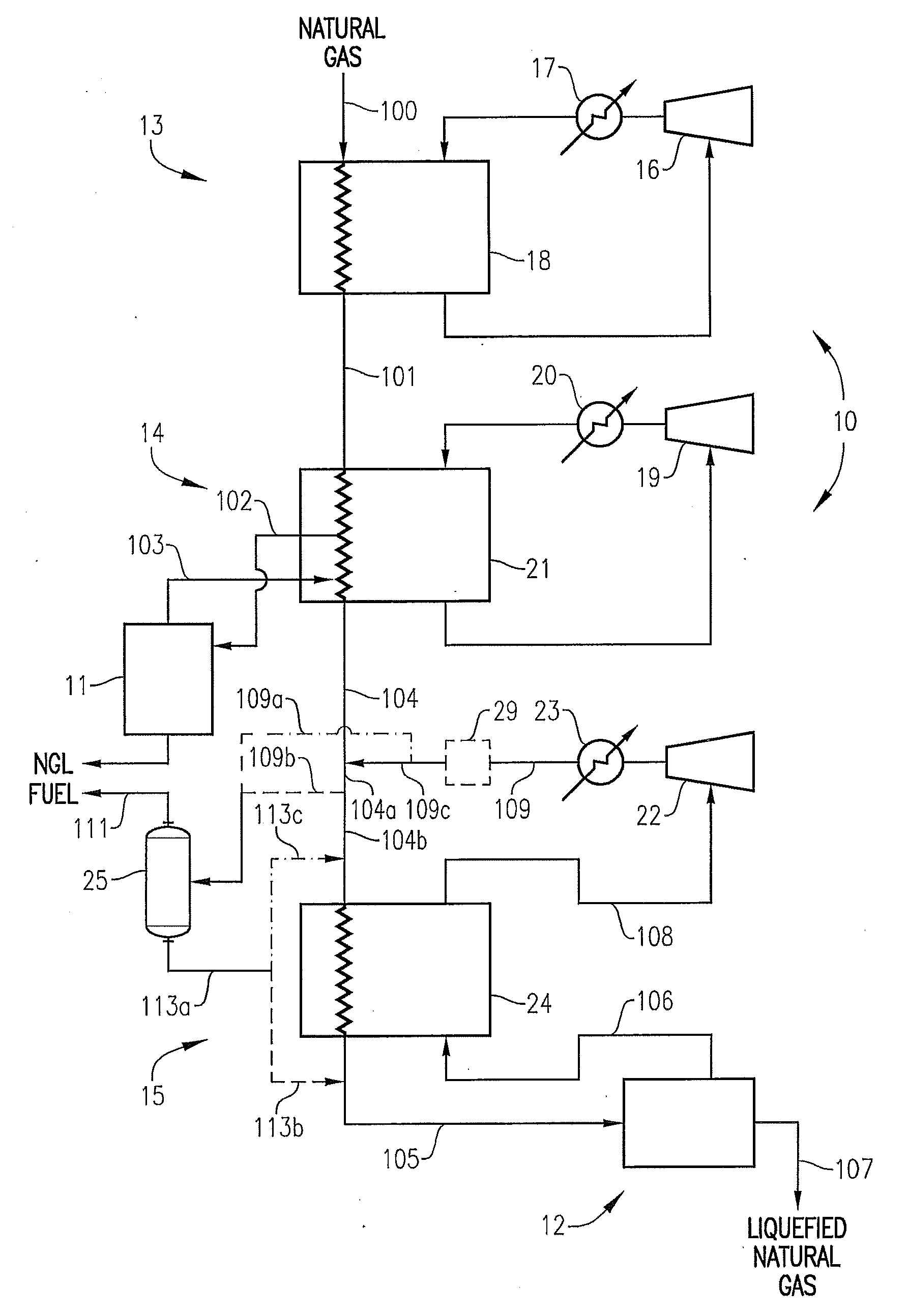
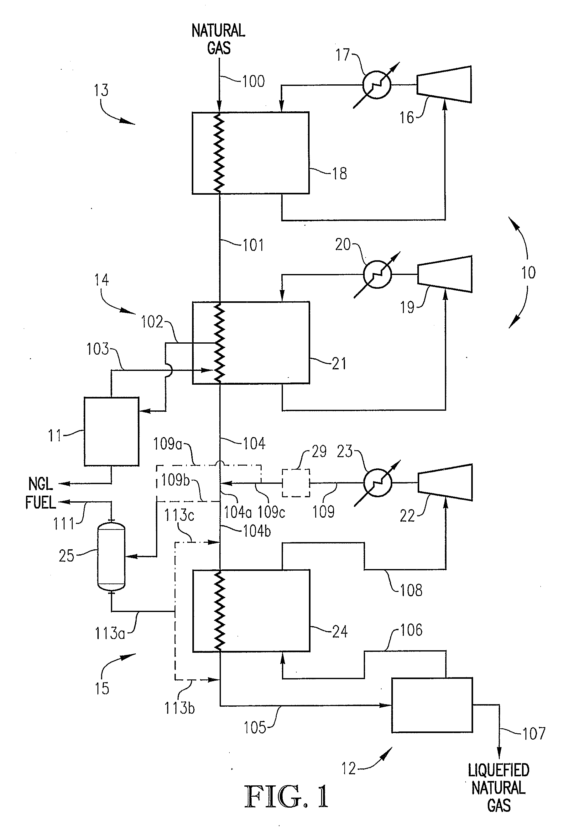
[0018]In accordance with one embodiment, the present invention can be implemented in a facility used to cool natural gas to its liquefaction temperature to thereby produce liquefied natural gas (LNG). The LNG facility generally employs one or more refrigerants to extract heat from the natural gas and then reject the heat to the environment. Numerous configurations of LNG systems exist, and the present invention may be implemented in many different types of LNG systems.

[0019]In one embodiment, the present invention can be implemented in a mixed refrigerant LNG system. Examples of mixed refrigerant processes can include, but are not limited to, a single refrigeration system using a mixed refrigerant, a propane pre-cooled mixed refrigerant system, and a dual mixed refrigerant system. In general, mixed refrigerants can comprise hydrocarbon and / or non-hydrocarbon components. Examples of suitable hydrocarbon components typically employed in mixed refrigerants can include, but are not limi...


PUM


Abstract

A liquefied natural gas (LNG) facility that employs a system to remove incondensable material from one or more refrigeration cycles within the facility. One or more embodiments of the present invention can be advantageously employed in an open-loop refrigeration cycle to remove at least a portion of one or more high vapor pressure components that have accumulated in the refrigerant cycle over time. In addition, several embodiments can be advantageously employed to stabilize facility operation in the event of drastic changes to the concentration of the natural gas feed stream introduced into the facility.

Description

CROSS-REFERENCE TO RELATED APPLICATIONS[0001]This application claims priority benefit under 35 U.S.C. Section 119(e) of U.S. Provisional Patent Ser. No. 61 / 095,189 filed on Sep. 8, 2008, the entire disclosure of which is incorporated herein by reference.BACKGROUND[0002]1. Field of the Invention[0003]This invention relates to methods and apparatuses for liquefying natural gas. In another aspect, the invention concerns a liquefied natural gas (LNG) facility employing a system for separating accumulated incondensable components from one or more refrigeration cycles in an LNG facility.[0004]2. Description of Related Art[0005]Cryogenic liquefaction is commonly used to convert natural gas into a more convenient form for transportation and / or storage. Because liquefying natural gas greatly reduces its specific volume, large quantities of natural gas can be economically transported and / or stored in liquefied form.[0006]Transporting natural gas in its liquefied form can effectively link a na...

Claims


Application Information

Patent Timeline
IPC IPC(8): F25J1/00
CPCF25J1/0022F25J1/004F25J1/0052F25J1/0072F25J1/0095F25J2220/64F25J1/023F25J1/0231F25J1/0249F25J2220/62F25J1/021F25J1/0085F25J1/0087
Inventor RANSBARGER, WELDON L.EVANS, MEGAN V.PRADERIO, ATTILIO J.MESSERSMITH, DAVID B.
Owner CONOCOPHILLIPS CO
Why Eureka
Try Eureka