Solar tracking and concentration device

a concentration device and solar tracking technology, applied in the direction of optical radiation measurement, instruments, comonautical navigation instruments, etc., can solve the problems of increasing the complexity of the operation, reducing reliability, and increasing so as to reduce the cost of fabricating, reduce the cost of manufacturing, and achieve the effect of reducing the cost of manufacturing

Active Publication Date: 2010-03-11
SUNPLUS MMEDIA
View PDF6 Cites 44 Cited by
  • Summary
  • Abstract
  • Description
  • Claims
  • Application Information

AI Technical Summary

Benefits of technology

[0009]Accordingly, the present invention is directed to a solar tracking and concentration device, which has preferred photoelectric conversion efficiency, and relatively simpler solar tracking mechanism, thereby reducing the fabricating cost.
[0011]The present invention is further directed to a solar concentration device, which has a simpler solar concentration mechanism and a lower fabricating cost.
[0018]In addition, the solar tracking and concentration device may further use a plurality of reflecting units, control the receiving unit to move along the first direction, and control the rotation angle of the receiving unit facing one of the plurality of reflecting units, according to the positions and the times of the reflecting units, such that the receiving unit may receive the sunlight reflected by the reflecting units at any moment under different times, so as to achieve a simple tracking mechanism. In other words, the solar tracking and concentration device of the present invention has a preferred photoelectric conversion efficiency, a simpler solar tracking mechanism, and a stable mechanical actuation. In addition, the present invention also provides a solar tracking and concentration method having the above-mentioned efficacies.

Problems solved by technology

However, in the conventional solar tracking and concentration device, usually the operation thereof is controlled by adopting a relatively complicated mechanical actuation, and thus the fabricating cost is increased and the complexity during the operation is increased, thereby reducing the reliability.

Method used


Image

  • Solar tracking and concentration device
  • Solar tracking and concentration device
  • Solar tracking and concentration device

Examples


first embodiment

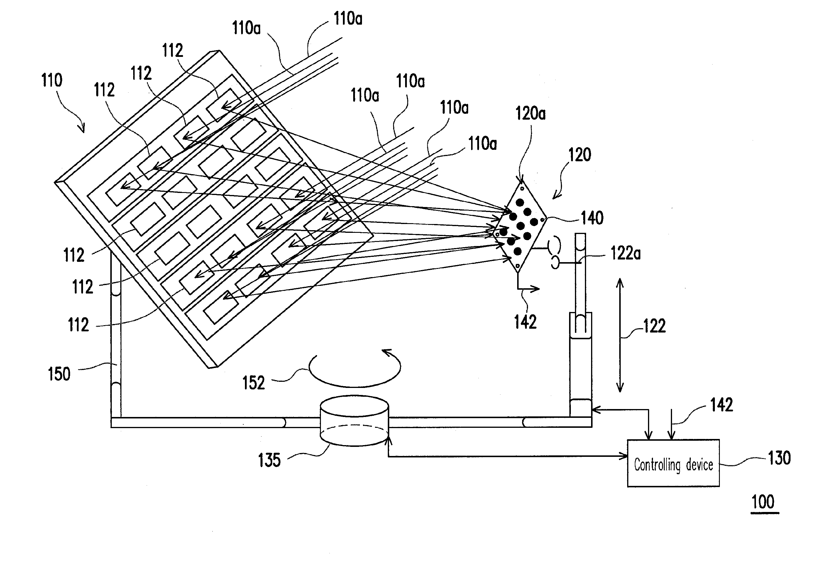
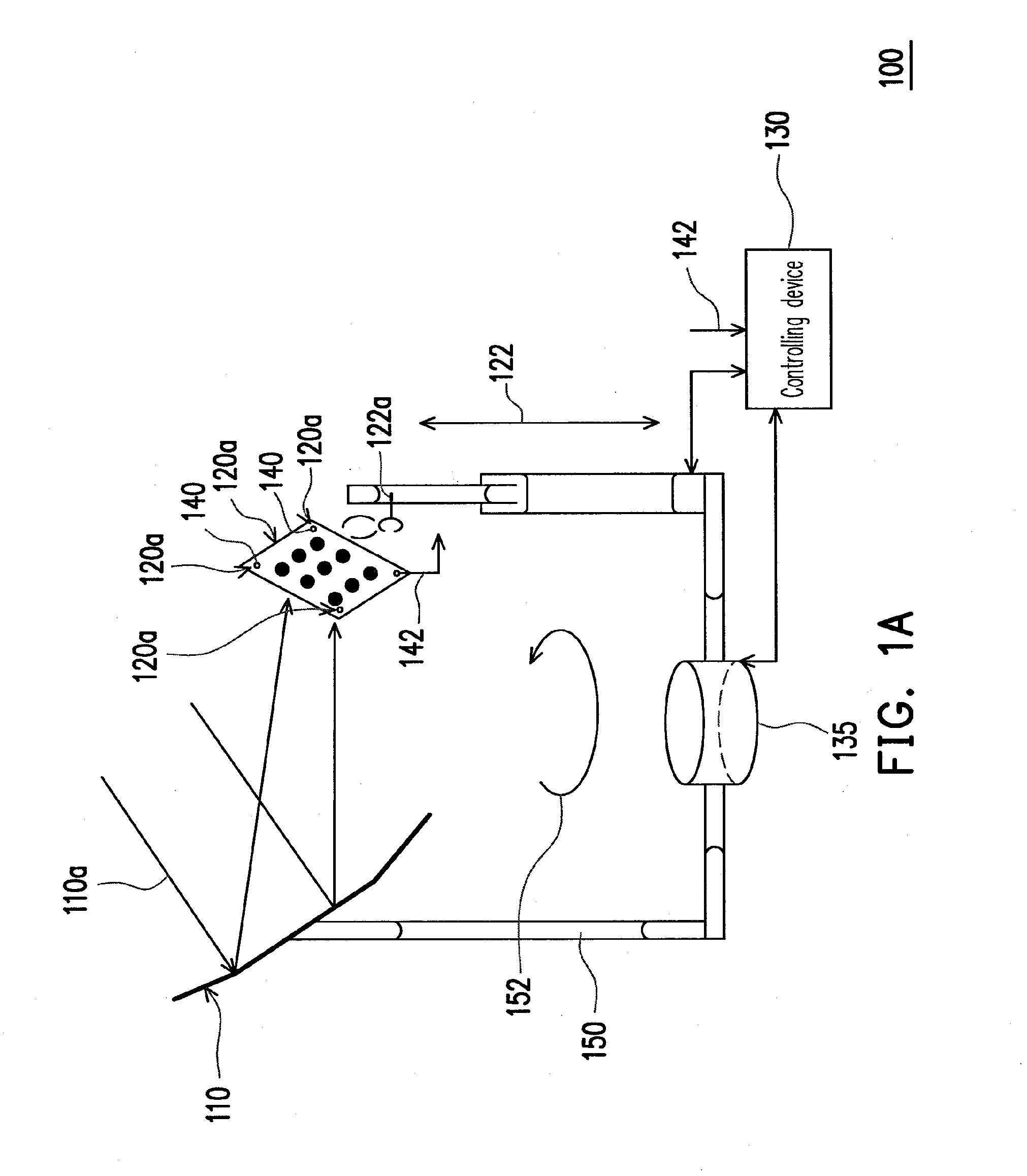
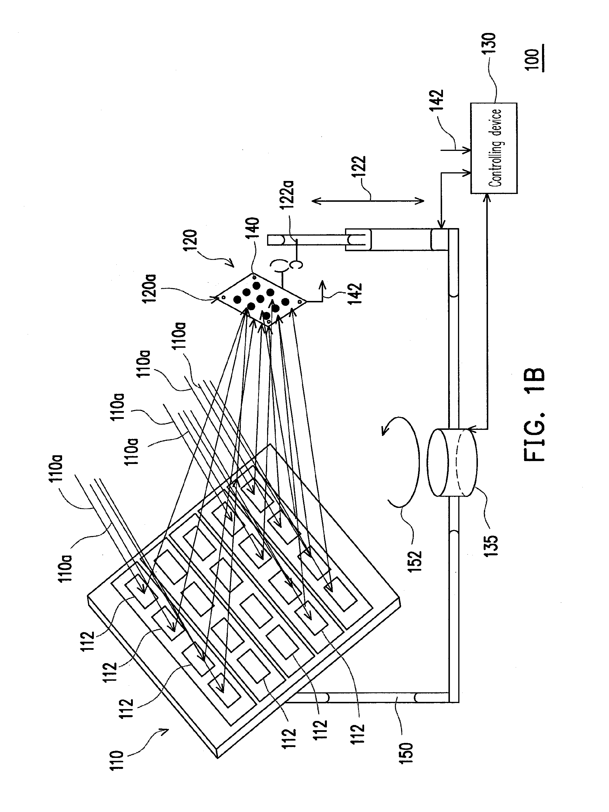
[0044]FIG. 1A is a schematic side view of a solar tracking and concentration device according to a first embodiment of the present invention. Referring to FIG. 1A, a solar tracking and concentration device 100 of this embodiment includes a reflecting unit 110, a receiving unit 120, a controlling device 130, and a plurality of photo sensors 140. The reflecting unit 110 reflects and concentrates sunlight 110a. The receiving unit 120 receives the sunlight 110a reflected by the reflecting unit 110. The receiving unit 120 and the reflecting unit 110 are disposed face to face, and the receiving unit 120 is adapted to move along a first direction 122, as shown in FIG. 1A.

[0045]Referring to FIG. 1A, the controlling device 130 controls a rotation angle 152 of a support element 150 and controls a first moving position 122a of the receiving unit 120 moving along the first direction 122, according to a position and a time of the reflecting unit 110. The support element 150 supports the reflecti...

second embodiment

[0095]FIG. 6A is a schematic side view of the solar tracking and concentration device according to a second embodiment of the present invention, and FIG. 6B is a schematic side view of the solar tracking and concentration device according to another embodiment. Referring to FIGS. 6A and 6B, a solar tracking and concentration device 200 or 200′ includes a plurality of reflecting units 210, a receiving unit 220, a controlling device 230, and a plurality of photo sensors 240.

[0096]In this embodiment, the solar tracking and concentration device 200 or 200′ adopts the concept similar to that of the solar tracking and concentration device 100 or 100′, except that the structure is partially different. For example, for the identical parts, the solar tracking and concentration device 200 or 200′ makes the receiving unit 220 move along the first direction 222 to receive the sunlight 110a reflected by the reflecting units 210 under different times. For the different parts, for example, the sol...

third embodiment

[0110]FIG. 7A is a schematic side view of the solar tracking and concentration device according to a third embodiment of the present invention, and FIG. 7B is a systematic block diagram of the solar tracking and concentration device of FIG. 7A. Referring to FIGS. 7A and 7B, a solar tracking and concentration device 300 of this embodiment includes a reflecting unit 310, a receiving unit 320, a controlling device 330, and an inclination sensing device 340.

[0111]In this embodiment, the reflecting unit 310 reflects and concentrates the sunlight 110a, and the reflecting unit 310 has a reflecting surface 312. Particularly, the reflecting unit 310 is, for example, the reflecting unit 110 or 210, and the related description may be obtained with reference to the above embodiment, so it is not repeated here.

[0112]In addition, the receiving unit 320 receives the sunlight 110a reflected by the reflecting unit 310, the receiving unit 320 has a receiving surface 322, and the receiving surface 322...


PUM


Abstract

A solar tracking and concentration device, including a reflecting unit, a receiving unit, a controlling device, and a plurality of photo sensors, is provided. The receiving unit is used to receive the sunlight reflected and reflected by the reflecting unit. The receiving unit and the reflecting unit face each other. The receiving unit is adapted to move along a first direction. According to the position and the time of the reflecting unit, the controlling device controls a rotation angle of a support element and controls a first moving position of the receiving unit moving along the first direction, in which the support element supports the reflecting unit and the receiving unit. The photo sensors are used to detect the sunlight reflected by the reflecting unit to the receiving unit, and are adapted to output a first feedback signal to calibrate a direction of the receiving unit facing the reflecting unit.

Description

CROSS-REFERENCE TO RELATED APPLICATION[0001]This application claims the priority benefit of Taiwan application serial no. 97134723, filed Sep. 10, 2008. The entirety of the above-mentioned patent application is hereby incorporated by reference herein and made a part of specification.BACKGROUND OF THE INVENTION[0002]1. Field of the Invention[0003]The present invention generally relates to a tracking and concentration device, in particular, to a solar tracking and concentration device.[0004]2. Description of Related Art[0005]Solar energy is a renewable and pollution free energy source, and is always the center of attention during the process of solving the recent pollution and shortage problem of the petrochemical energy source. Particularly, a solar panel has a photovoltaic cell (PV cell), so the solar panel may directly convert the optical energy to the electric energy. However, recently it is a quite important research topic how to make the solar panel have the higher photoelectric...

Claims


Application Information

Patent Timeline
Patent Type & Authority Applications(United States)
IPC IPC(8): F24J2/38F24J2/10F24S23/70F24S50/20
CPCF24J2/10F24J2/38F24J2/407F24J2/523F24J2/5406H01L31/0547F24J2/5431F24J2002/385G05D3/105Y02E10/52Y02E10/47F24J2/542F24S23/70F24S25/10F24S30/422F24S30/452F24S30/48F24S50/20F24S50/80F24S2050/25
Inventor CHANG, YI-CHIEHCHEN, YARN-CHEN
Owner SUNPLUS MMEDIA
Why Eureka
Try Eureka