Down-the-hole drill hammer having a reverse exhaust system and segmented chuck assembly

a reverse exhaust system and drill hammer technology, which is applied in the field of drill hammer having a reverse exhaust system and segmented chuck assembly, can solve the problems of reducing the overall power and affecting the performance of the tool, and requiring a lot more air than is needed to clean the bit-end of the hammer

a reverse exhaust system and drill hammer technology, which is applied in the field of drill hammer having a reverse exhaust system and segmented chuck assembly, can solve the problems of reducing the overall power and affecting the performance of the tool, and requiring a lot more air than is needed to clean the bit-end of the hammer

US20100059284A1Active Publication Date: 2010-03-11CENTER ROCK INC

Image

  • Down-the-hole drill hammer having a reverse exhaust system and segmented chuck assembly
  • Down-the-hole drill hammer having a reverse exhaust system and segmented chuck assembly
  • Down-the-hole drill hammer having a reverse exhaust system and segmented chuck assembly

Examples


Embodiment Construction

[0032]Certain terminology is used in the following description for convenience only and is not limiting. The words “right,”“left,”“upper,” and “lower” designate directions in the drawings to which reference is made. For purposes of convenience, “distal” is generally referred to as toward the drill bit end of the DHD hammer, and “proximal” is generally referred to as toward the backhead end of the DHD hammer. “Superior” means generally above or top, while “inferior” means generally below or bottom. Unless specifically set forth herein, the terms “a,”“an” and “the” are not limited to one element but instead should be read as meaning “at least one.” The terminology includes the words above specifically mentioned, derivatives thereof, and words of similar import.

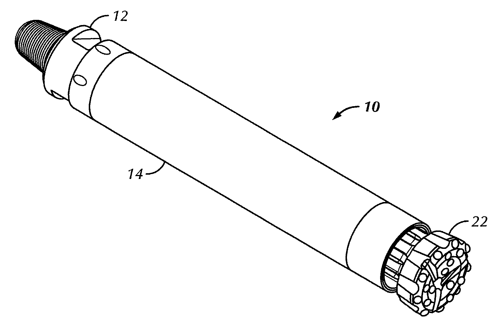
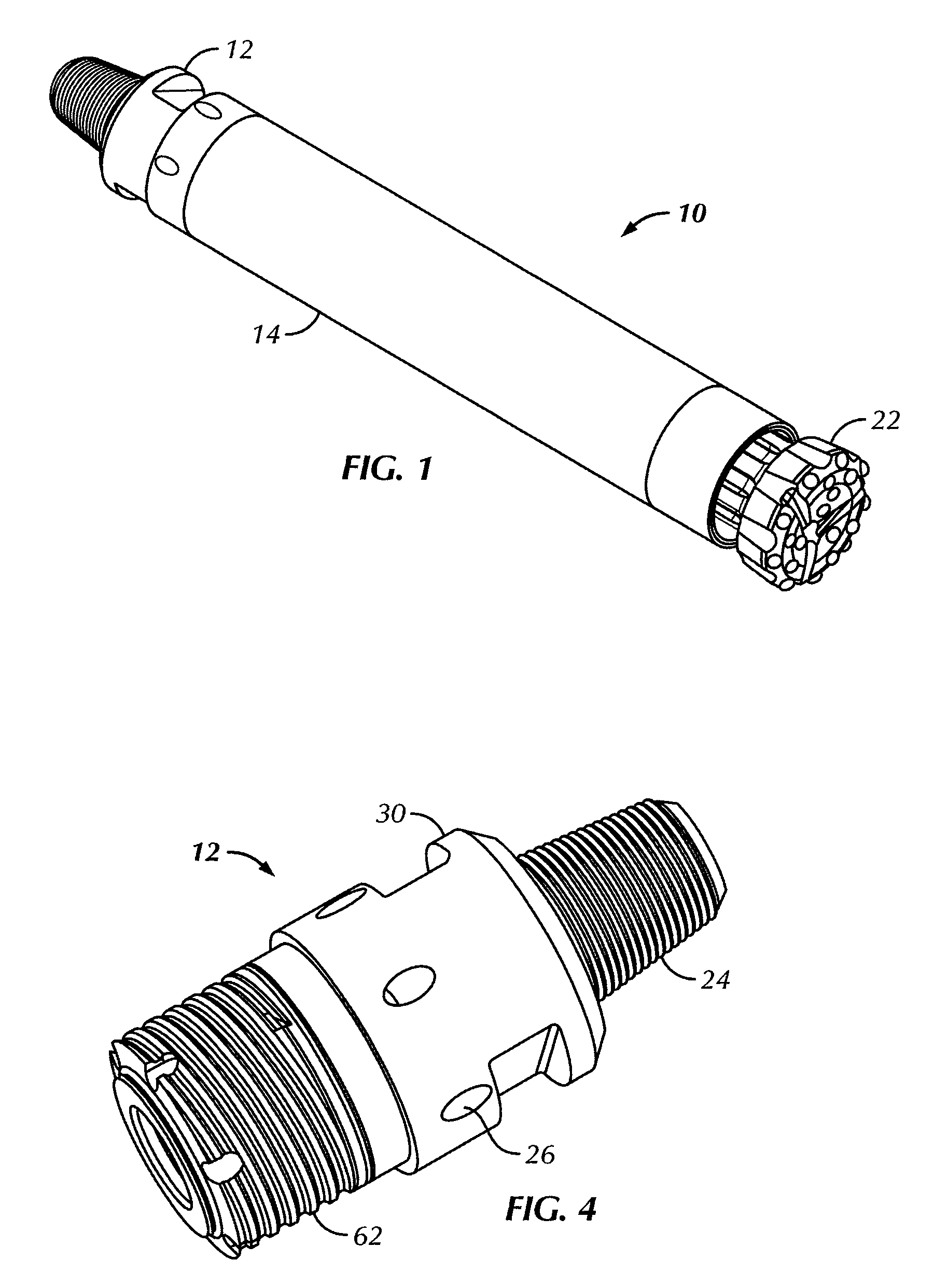
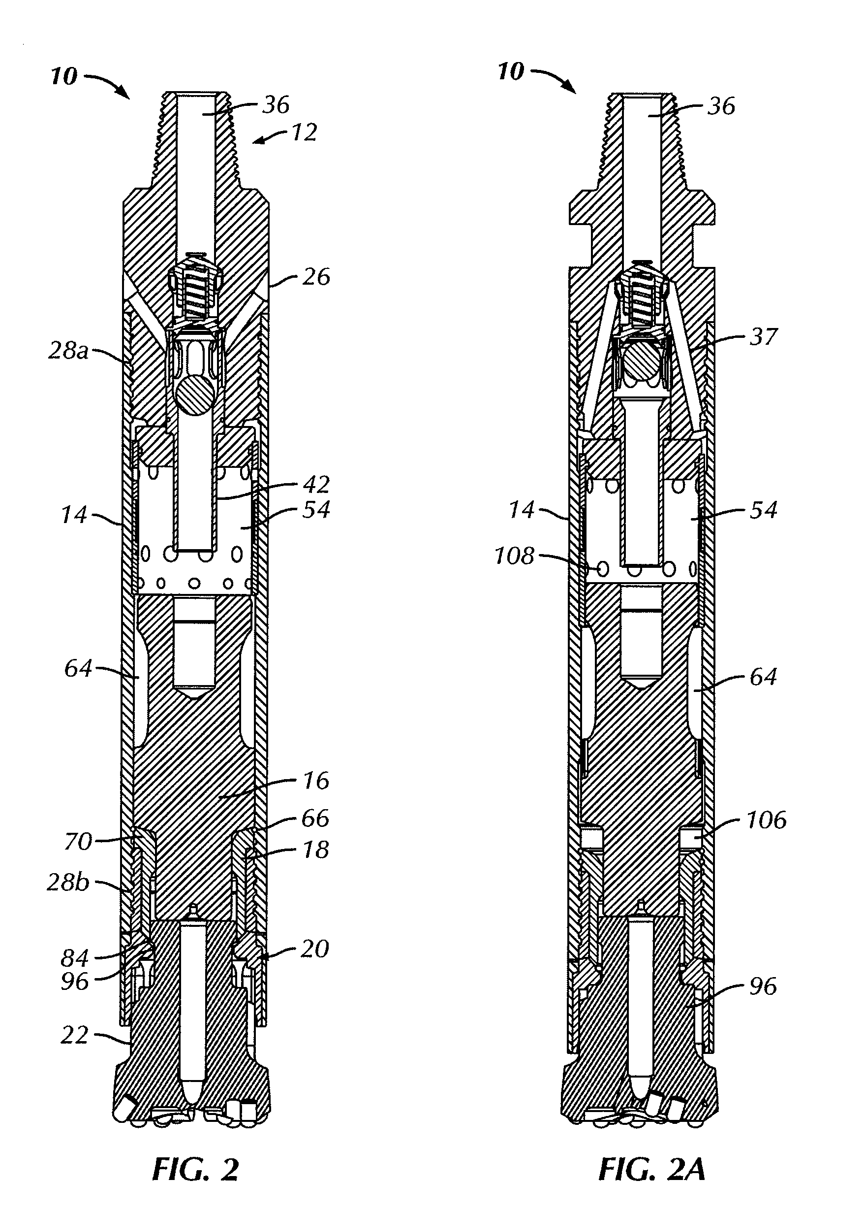
[0033]In a preferred embodiment, the present invention provides for a DHD hammer 10, as shown in FIGS. 1-4, for use with a conventional down-the-hole drill pipe (not shown). The DHD hammer 10 includes a backhead 12, a housing 14...


PUM


Abstract

A down-the-hole drill hammer is provided that includes a housing, a solid core piston mounted within the housing, a seal located between the solid core piston and the housing, and a backhead configured to exhaust working fluid volumes about a proximal end of the DHD hammer. The backhead includes a check valve assembly having a plug seal that can be moved to a closed seal position by gravity. A DHD hammer having a segmented chuck assembly is also provided. The segmented chuck assembly includes a plurality of chuck segments forming a cylindrical chuck assembly.

Description

CROSS REFERENCE TO RELATED APPLICATIONS[0001]The present application is a continuation-in-part of pending U.S. patent application Ser. No. 12 / 361,263, filed Jan. 28, 2009, entitled “Down-the-Hole Drill Reverse Exhaust System” and pending International Application No. PCT / US2009 / 38957 filed Mar. 31, 2009, which claims the benefit of priority pursuant to 35 U.S.C. §119(e) of U.S. Provisional Patent Application No. 61 / 040,817, filed Mar. 31, 2008, the entire disclosures of which are hereby incorporated herein by reference.BACKGROUND OF THE INVENTION[0002]The present invention relates to a down-the-hole drill (“DHD”) hammer. In particular, the present invention relates to a DHD hammer having a reverse exhaust system and a segmented chuck assembly.[0003]Typical DHD hammers include a piston that is moved cyclically with high pressure gas (e.g., air). The piston generally has two end surfaces that are exposed to working air volumes i.e., a return volume and a drive volume that are filled a...

Claims


Application Information

Patent Timeline
11 Mar 2010
Publication
US20100059284A1
IPC
E21B4/14; E21B1/38; B23B31/16
CPC
Y10T279/17863; E21B4/14; E21B4/06; E21B10/36; B25D17/08
Inventors
LYON, LELAND H.; LAY, WARREN THOMAS