Electromagnetic rotor machine

Inactive Publication Date: 2010-03-11
NORDGREN ROBERT
View PDF6 Cites 9 Cited by
  • Summary
  • Abstract
  • Description
  • Claims
  • Application Information

AI Technical Summary

Benefits of technology

[0003]An object of the present invention is to develop further a rotor machine of the above defined type, in order that it

Problems solved by technology

As the torque of the motor and its radius are directly related, the motor will have a large diameter an

Method used


Image

  • Electromagnetic rotor machine
  • Electromagnetic rotor machine
  • Electromagnetic rotor machine

Examples


Embodiment Construction

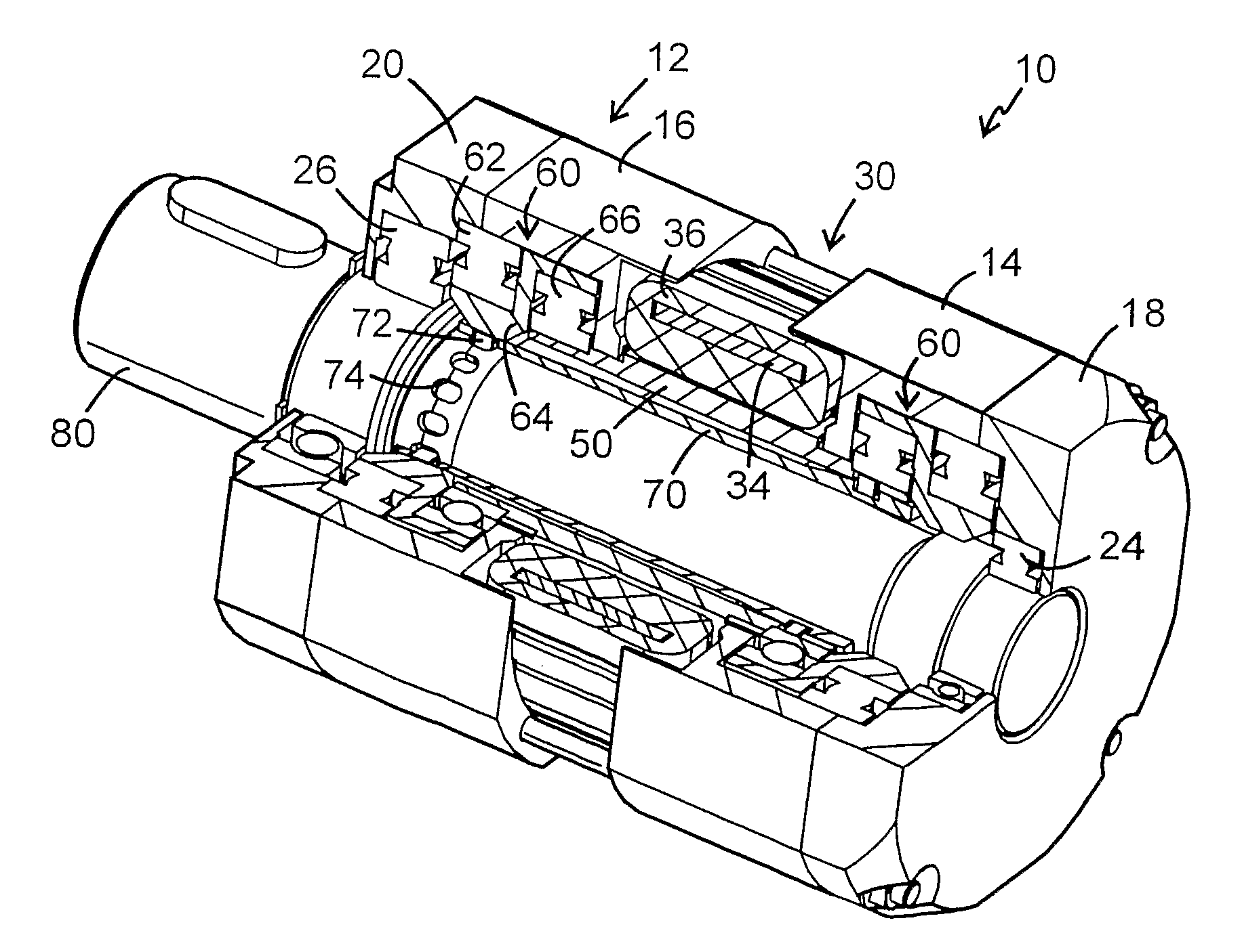
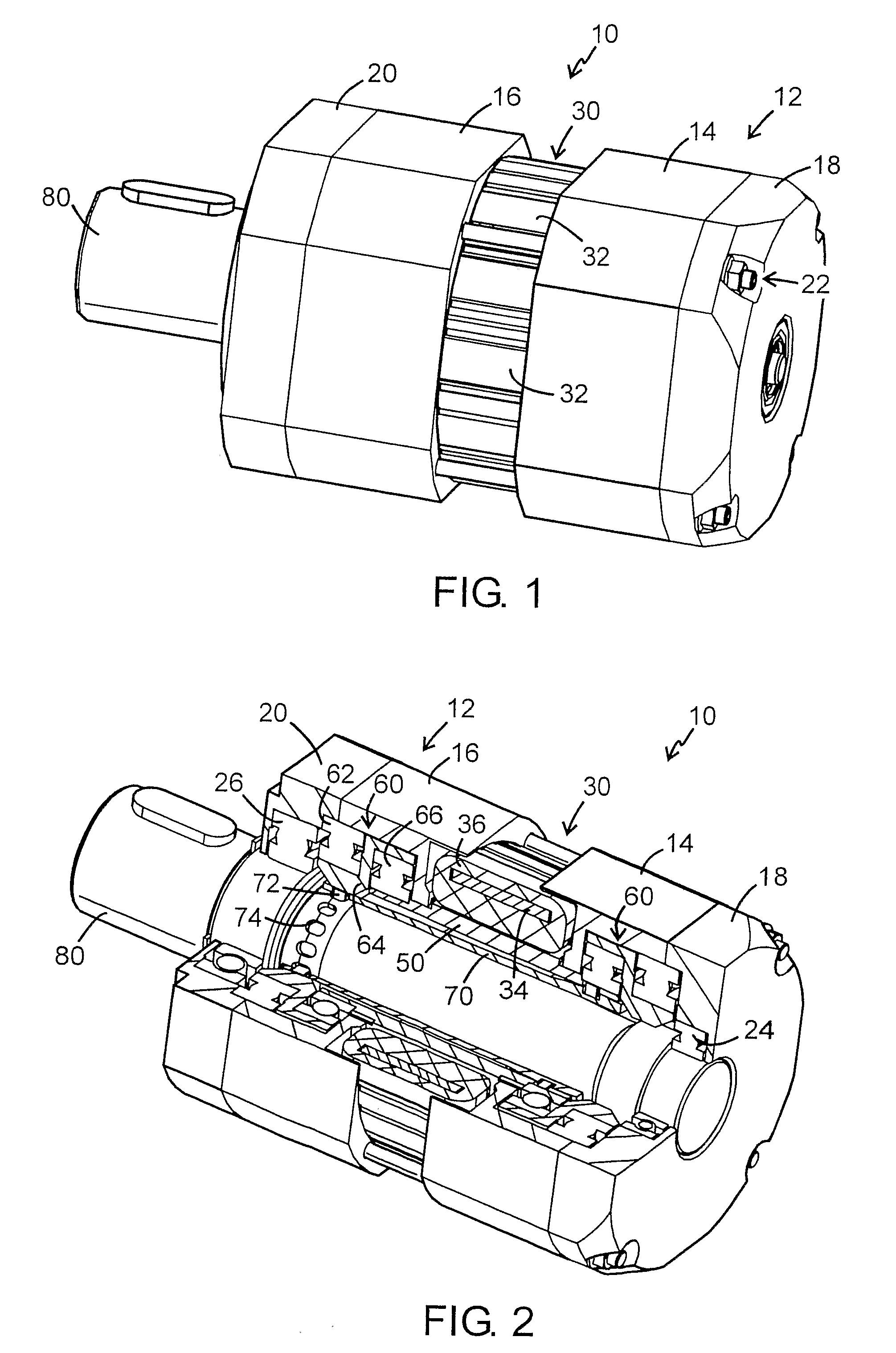
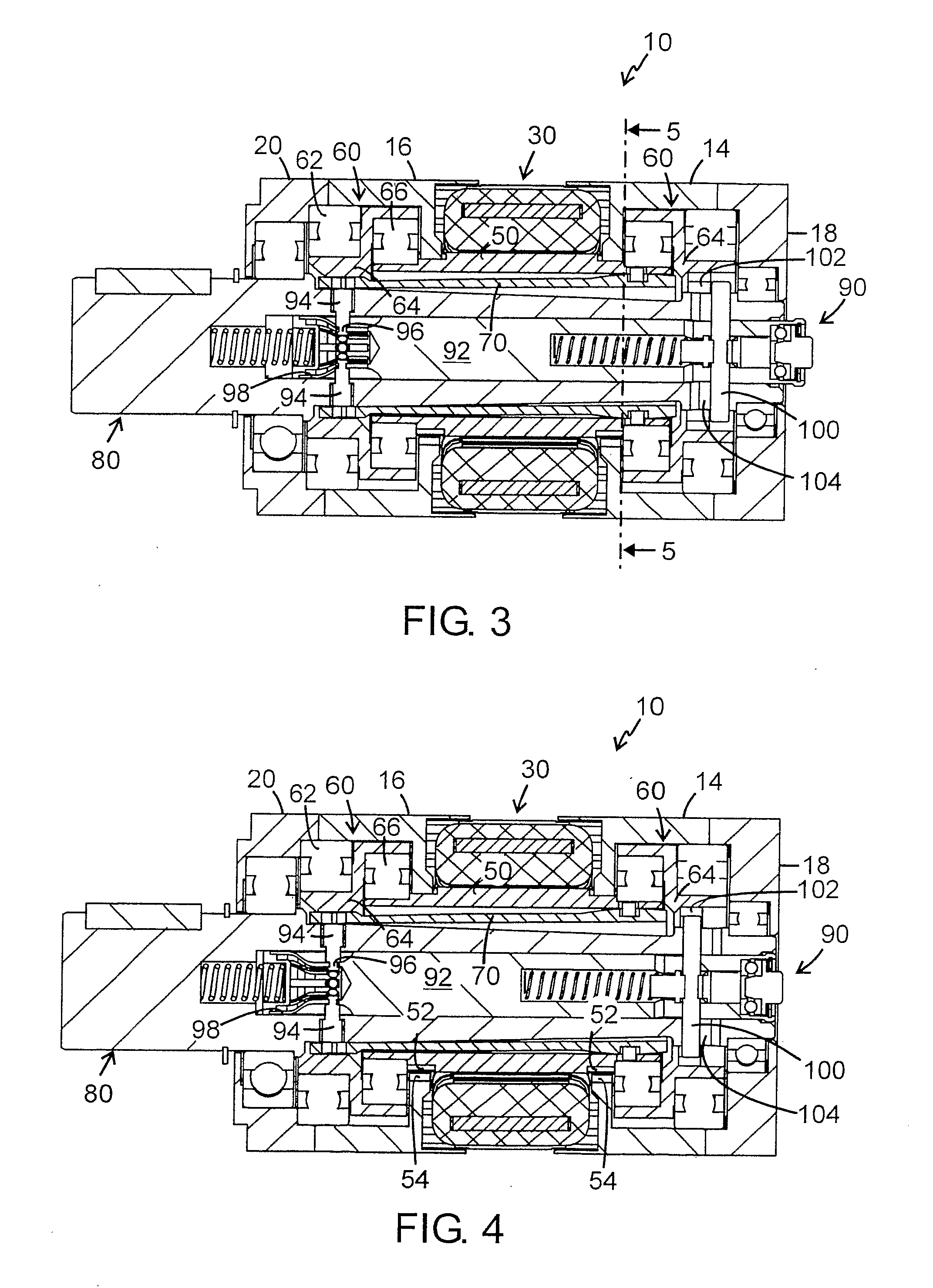
[0021]The embodiment of the rotor machine 10 shown in FIG. 1 comprises a machine housing 12 having an inner pair of machine covers or end plates 14, 16 and outer pair end plates 18, 20 connected together by a plurality of bolt assemblies 22. An annular stator 30 is supported between the end plates 14, 16.

[0022]The machine has a rotor 50 adapted to perform an orbiting motion inside the machine housing 12.

[0023]While the machine 10 may be arranged as a pure generator, in the examples shown it is supposed to be arranged as a motor 10. By a control system (not shown) the motor 10 can also have a generator function, for example for the recovery of brake energy.

[0024]As is apparent for example from FIG. 6, the annular stator 30 is provided in the shape of a plurality (twelve) of electromagnets 32 distributed around the periphery and each consisting of a core 34 and a coil 36, while the rotor is made of a magnetic material. The magnets 32 are magnetically separated from each other by gaps ...


PUM


Abstract

An electromagnetic rotor machine (10) of the hypocycloid type comprising a machine housing (12), an annular stator (30) in the machine housing an annular rotor (50) of a magnetic material, which is supported orbiting and rotationally around it's own axis in the machine housing, and at an interior side thereof adapted to operatively engage a drive element supported in the machine housing. The stator (30) comprises circumferentially arranged electromagnets which are magnetically separated from each other, each of said magnets comprising a core (34) and a coil (36) and being arranged in such a number that a plurality of magnets always is located at a side of the rotor (50).

Description

TECHNICAL AREA[0001]The present invention relates to an electromagnetic rotor machine of the hypocycloid type. Such machines are known, for example from U.S. Pat. Nos. 2,761,079, 3,560,774, 4,482,828 and 5,703,422.BACKGROUND[0002]For example, electrical fork lift trucks are normally powered by conventional DC motors. The development of power electronics has made asynchronous motors more common. The torque requirements are so high that the power train includes a gear transmission. Other types of motors such as servo motors magnetized by permanent magnets and SR (Switched Reluctance) motors have also been tested. Applications using direct drives without any transmission between motor and driving wheels can also be found. As the torque of the motor and its radius are directly related, the motor will have a large diameter and a high cost. In systems having a fixed transmission ratio, the maximum speed is limited by the physical limits for the motor speed. In DC drives the power electron...

Claims


Application Information

Patent Timeline
IPC IPC(8): H02K41/06H02K7/00
CPCH02K41/06
Inventor NORDGREN, ROBERT
Owner NORDGREN ROBERT
Why Eureka
Try Eureka