Method and apparatus for automatically identifying electrical parameters in a sensor-less pmsm

Active Publication Date: 2010-03-11
ROCKWELL AUTOMATION TECH
View PDF10 Cites 42 Cited by
  • Summary
  • Abstract
  • Description
  • Claims
  • Application Information

AI Technical Summary

Benefits of technology

[0009]The present invention provides an effective parameter estimation system for sensor-less permanent magnet synchronous machines operating during initial commissioning without the need to know other machine parameters. The

Problems solved by technology

The signal injection method does not need machine parameters; however, it has limitations caused by the extra losses due to the injected high frequency carriers.
Consequently, most model-based methods fail at low and zero speeds because back-EMF is speed dependent.
Current metho

Method used


Image

  • Method and apparatus for automatically identifying electrical parameters in a sensor-less pmsm
  • Method and apparatus for automatically identifying electrical parameters in a sensor-less pmsm
  • Method and apparatus for automatically identifying electrical parameters in a sensor-less pmsm

Examples


Embodiment Construction

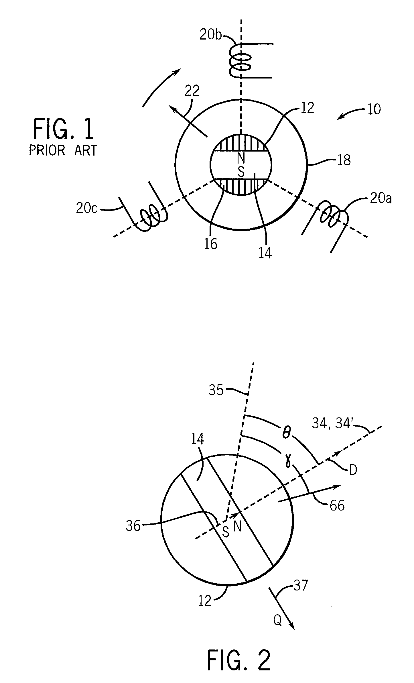
[0038]Referring now to FIG. 1, a sensor-less PMSM motor 10 provides a rotor 12 attached to a rotatable shaft (not shown) for rotation about an axis through the center of the rotor 12 perpendicular to the plane of the figure. The rotor 12 includes a permanent magnet 14 and ferromagnetic flux directors 16. For clarity, a rotor having a single pole pair (e.g. only a single north and south pole) is shown; however, it will be understood that the present invention is equally applicable to multi-pole rotors.

[0039]The rotor 12 may be surrounded by a stator 18 having one or more coils 20a, 20b, and 20c shown here positioned at regular angles of 120° about the rotor 12. Again additional coils may be provided according to techniques well known in the art for motors having larger numbers of poles.

[0040]Generally, appropriately phased signals may be applied to each of coils 20a, 20b and 20c to produce a rotating magnetic field vector 22 synchronously attracting the rotor 12 to drive the motor 10...


PUM


Abstract

A method and apparatus for determining electrical parameters for commissioning a sensor-less permanent magnet synchronous machine uses knowledge of the rotor position to apply balanced pulses along the rotor magnet axis and perpendicular to the rotor magnet axis allowing measurement of q- and d-inductance at multiple current levels without substantial rotor movement.

Description

BACKGROUND OF THE INVENTION[0001]The present invention relates to electric motors and, in particular, to permanent magnet synchronous machines (PMSM) and, more particularly, to a method and apparatus for automatically identifying electrical parameters in sensor-less PMSMs.[0002]Permanent magnet synchronous machines are electric motors having a rotor holding a permanent magnet that may turn about an axis within a stator. The stator holds conductive coils that may be energized to create a rotating magnetic field. The rotating magnetic field is coordinated with the rotor position to draw the rotor along synchronously.[0003]Simple PMSMs employ power transistors to switch the electrical currents in the stator coils to create the necessary rotating magnetic field. “Sensor-less” PMSMs eliminate the rotor position sensors and deduce rotor position from its effect on the electrical signals used to drive the stator coils.[0004]Most motor drives for sensor-less PMSMs deduce rotor position usin...

Claims


Application Information

Patent Timeline
IPC IPC(8): H02P21/14
CPCH02P21/14
Inventor LIU, JINGBOHARBAUGH, MARK M.NONDAHL, THOMAS A.SCHMIDT, PETER B.ROYAK, SEMYON
Owner ROCKWELL AUTOMATION TECH
Why Eureka
Try Eureka