Liquid crystal display device

a liquid crystal display and display device technology, applied in static indicating devices, instruments, optics, etc., can solve the problem of large thickness of the display device as a whole, and achieve the effect of reducing the manufacturing cost of the liquid crystal display device, preventing interference, and effective use of spa

Active Publication Date: 2010-03-11
JAPAN DISPLAY INC +1
View PDF3 Cites 121 Cited by
  • Summary
  • Abstract
  • Description
  • Claims
  • Application Information

AI Technical Summary

Benefits of technology

[0012]The task of the present invention lies in the realization of the constitution of a liquid crystal display device having a touch panel and a front window which can reduce a thickness and a size of an external shape thereof without damaging reliability.
[0020]According to the present invention, in the liquid crystal display device which includes the touch panel and the front window, the electronic parts are mounted on a lower side of the touch-panel-use flexible printed circuit board, the electronic parts are mounted on a lower side of the main flexible printed circuit board, and the portions of the respective boards on which the electronic parts are mounted are arranged below the front window and hence, it is possible to effectively use a space thus realizing the miniaturization of a setting of a mobile phone or the like. Further, it is possible to prevent the interference between the electronic parts mounted on the touch-panel-use flexible printed circuit board and the electronic parts mounted on the main flexible printed circuit board.
[0021]Further, according to the present invention, when a front window and a touch panel are separated from a liquid crystal display device and are repaired, a relatively expensive LED can be reproduced thus realizing the reduction of manufacturing cost of the liquid crystal display device as a whole.

Problems solved by technology

On the other hand, the use of the touch panel and the front window brings about the drawback that a thickness of the display device becomes large as a whole.

Method used


Image

  • Liquid crystal display device
  • Liquid crystal display device
  • Liquid crystal display device

Examples


embodiment 1

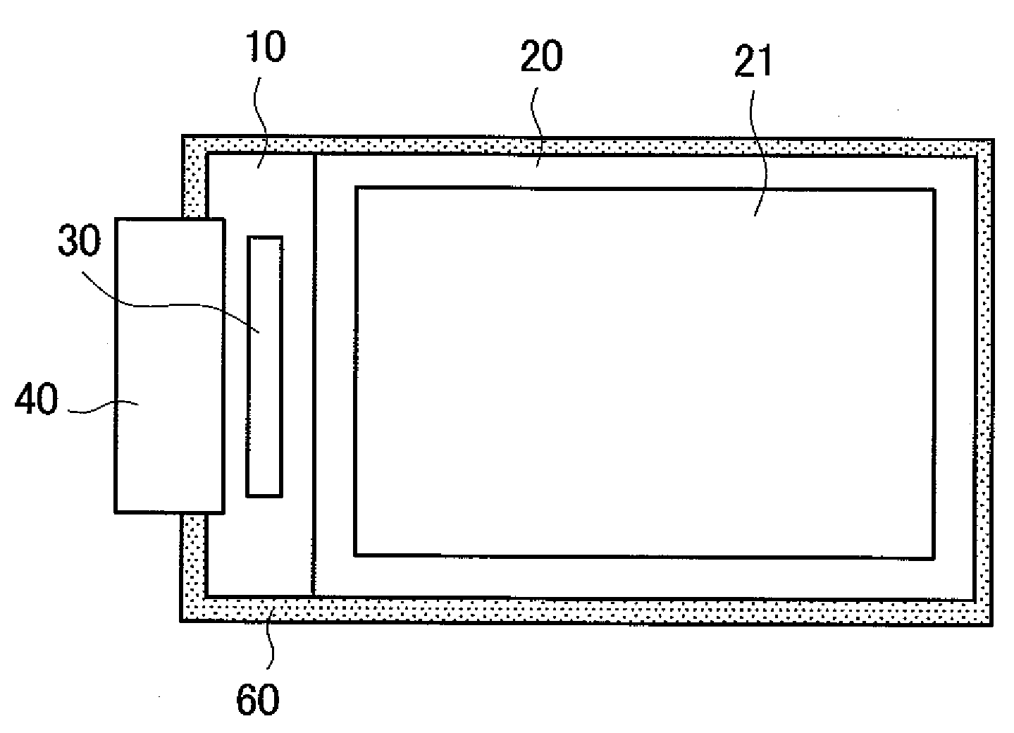
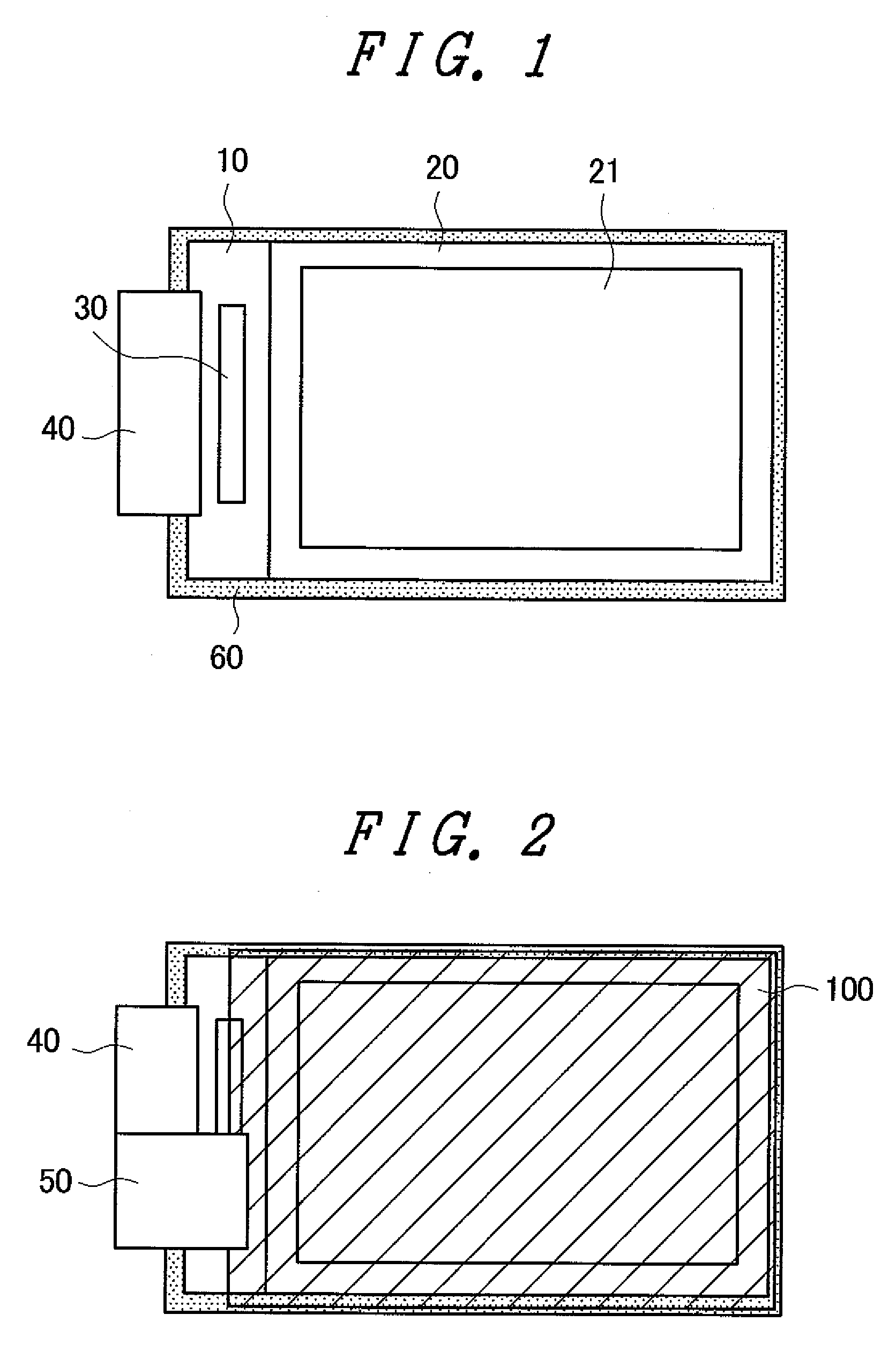
[0034]FIG. 1 is a plan view of a liquid crystal display panel according to the present invention which is used for a mobile phone or the like. In FIG. 1, a color filter substrate 20 is mounted on a TFT substrate 10. A liquid crystal layer not shown in the drawing is sandwiched between the TFT substrate 10 and the color filter substrate 20. The TFT substrate 10 and the color filter substrate 20 are adhered to each other by a sealing material not shown in the drawing which is formed between picture frame portions of these substrates. The TFT substrate 10 is larger than the color filter substrate 20 in size, and a terminal portion for supplying electricity, video signals, scanning signals and the like to the liquid crystal display panel is formed on a portion of the TFT substrate 10 which is formed by making the TFT substrate 10 larger than the color filter substrate 20.

[0035]An IC driver 30 for driving scanning lines, video signal lines and the like is formed on the terminal portion. ...

embodiment 2

[0081]FIG. 7 is a perspective view of a main flexible printed circuit board 40 which is used in a second embodiment of the present invention. In FIG. 7, a light-emitting-diode-use flexible printed circuit board 45 on which light emitting diodes 70 are arranged is branched from the main flexible printed circuit board 40. In FIG. 7, the light-emitting-diode-use flexible printed circuit board 45 is folded back and extends along a back surface of a backlight not shown in the drawing.

[0082]In FIG. 7, three light emitting diodes 70 are arranged on the branched light-emitting-diode-use flexible printed circuit board 45. The main flexible printed circuit board 40 is not folded back and extends frontwardly, and electronic parts not shown in the drawing are arranged on a lower side of the main flexible printed circuit board 40.

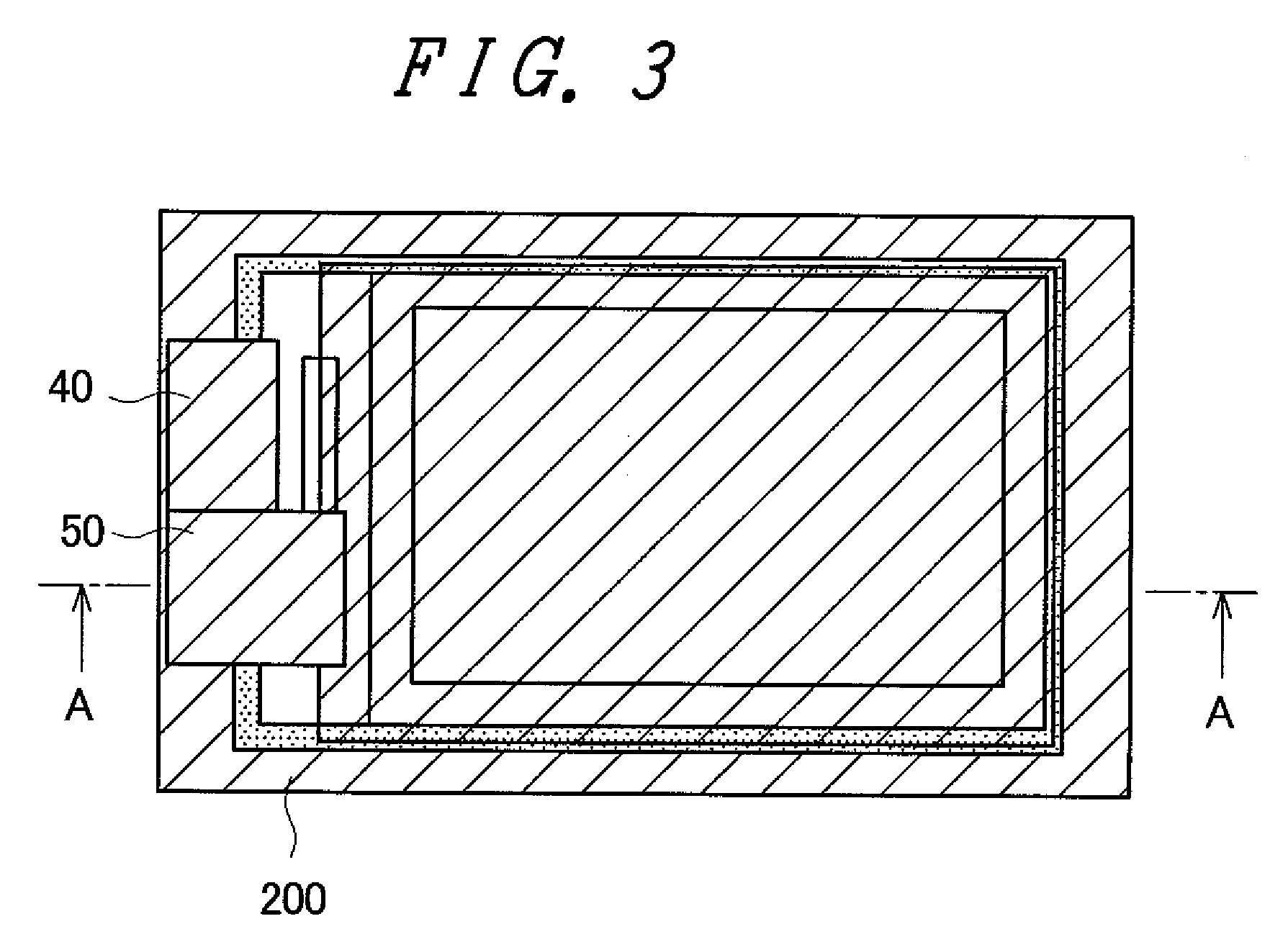
[0083]FIG. 8 is a plan view showing a state where the main flexible printed circuit board 40 having such a constitution is mounted on a liquid crystal display device. I...


PUM


Abstract

A liquid crystal display device having a touch panel and a front window which can enhance reliability thereof and facilitates repair thereof is provided. The touch panel and the front window are mounted on a liquid crystal display device using a thermoplastic adhesive material. Electronic parts are arranged on a lower side of a touch-panel-use flexible printed circuit board, and electronic parts are arranged on a lower side of a main flexible printed circuit board. The respective electronic parts are covered with the front window in a plan view. A light emitting diode is mounted on the main flexible printed circuit board, and faces a light guide plate in a resin mold. Due to such a constitution, an external shape of the liquid crystal display device can be made small as a whole, and relatively expensive light emitting diodes can be reproduced and reused by repair.

Description

CROSS-REFERENCE TO RELATED APPLICATION[0001]The disclosure of Japanese Patent Application No. 2008-228696 filed on Sep. 5, 2008, including the specification, drawings and abstract is incorporated herein by reference in its entirety.BACKGROUND OF THE INVENTION[0002]1. Field of the Invention[0003]The present invention relates to a liquid crystal display device, and more particularly to a miniaturized display device having a touch panel which is used in a mobile phone or the like.[0004]2. Description of the Related Art[0005]A liquid crystal display device includes a TFT substrate on which pixel electrodes, thin film transistors (TFT) and the like are formed in a matrix array, a color filter substrate which faces the TFT substrate in an opposed manner and forms color filters and the like thereon at positions corresponding to the pixel electrodes formed on the TFT substrate, and liquid crystal which is sandwiched between the TFT substrate and the color filter substrate. An image is forme...

Claims


Application Information

Patent Timeline
Patent Type & Authority Applications(United States)
IPC IPC(8): G06F3/041G09G3/36
CPCG02F1/133308G02F1/13338G02F1/133615G02F1/13452H05K2201/10106H05K1/147H05K1/189H05K2201/052G06F3/0412
Inventor OOHIRA, EIJI
Owner JAPAN DISPLAY INC
Why Eureka
Try Eureka