Storage device and control circuit

a technology of storage device and control circuit, which is applied in the direction of data recording, instruments, magnetic recording, etc., can solve the problems of increased process time, vibration of magnetic disk device, head positioning error,

Inactive Publication Date: 2010-03-11
TOSHIBA STORAGE DEVICE CORP
View PDF18 Cites 28 Cited by
  • Summary
  • Abstract
  • Description
  • Claims
  • Application Information

AI Technical Summary

Problems solved by technology

In general, when a magnetic disk device is mounted in a rack of a storage system, the magnetic disk device is affected by a vibration of a fan or another disk.
The twisting vibration causes the rotary actuator rotatably supported by a pivot shaft to move in the rotation direction, and forms disturbance that causes a head positioning error.
As a result, the manufacturing cost of the magnetic disk device or a process time is increased.
However, since the two shock sensors are provided, two ADCs need to be provided, resulting in an increase in the manufacturing cost.
However, in the time-sharing ADC 126, the cost is high and the process time is increased twice, which results in increasing a load of the MPU 110 and decreasing a sampling frequency by an AD conversion.

Method used


Image

  • Storage device and control circuit
  • Storage device and control circuit
  • Storage device and control circuit

Examples


first embodiment

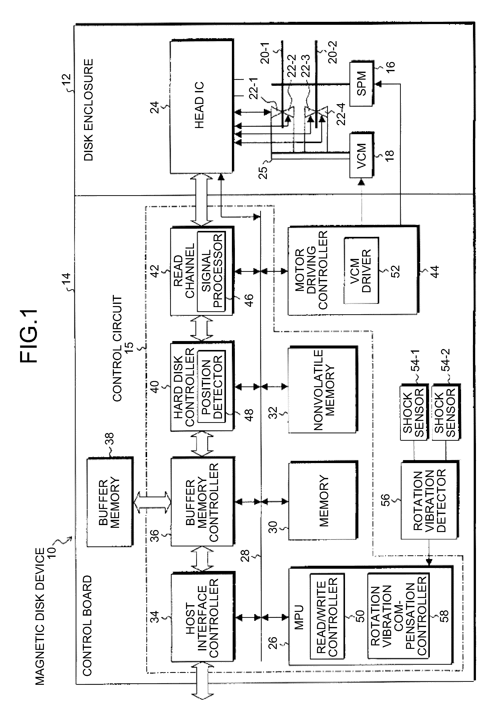
[0058]FIG. 3 illustrates rotation vibration compensation control according to the invention. In FIG. 3, a servo signal on the magnetic disk 20 detected by the head 22 is demodulated by the signal processor 46, the servo signal is converted into a head position signal by the position detector 48 and read by the MPU 26, and the head 22 is moved to seek a desired track and the on-track is performed. In this state, to eliminate an error of the head position signal with respect to the target position, i.e., an error with respect to the center of the track, the MPU 26 drives the voice coil motor 18 by the VCM driver 52, and performs on-track control to move the head 22 to the center of the target track by the rotary actuator 25.

[0059]To perform rotation vibration compensation control with respect to the on-track control of the head 22, the shock sensors 54-1 and 54-2, the rotation vibration detector 56, and the rotation vibration compensation controller 58 are provided. In the rotation vi...

second embodiment

[0077]FIG. 7 illustrates rotation vibration compensation control according to the invention. As illustrated in FIG. 7, the control circuit 15 comprises digital-to-analog converters (DACs) 90-1 and 90-2 in addition to the signal processor 46, the position detector 48, and the MPU 26.

[0078]Meanwhile, the rotation vibration detector 56 comprises, similarly to that of the first embodiment illustrated in FIG. 3, amplifiers 68-1 and 68-2 to amplify vibration detection signals from the shock sensors 54-1 and 54-2, the analog operation circuit 70 to perform a differential operation, and the ADC 72. However, output signals VDAC1 and VDAC2 from the DACs 90-1 and 90-2 in the control circuit 15 are input to the analog operation circuit 70.

[0079]FIG. 8 is a circuit diagram of the rotation vibration detector 56 of the second embodiment. As illustrated in FIG. 8, the circuit part comprising the shock sensors 54-1 and 54-2, the amplifiers 68-1 and 68-2, and the operational amplifier 74, the input r...

third embodiment

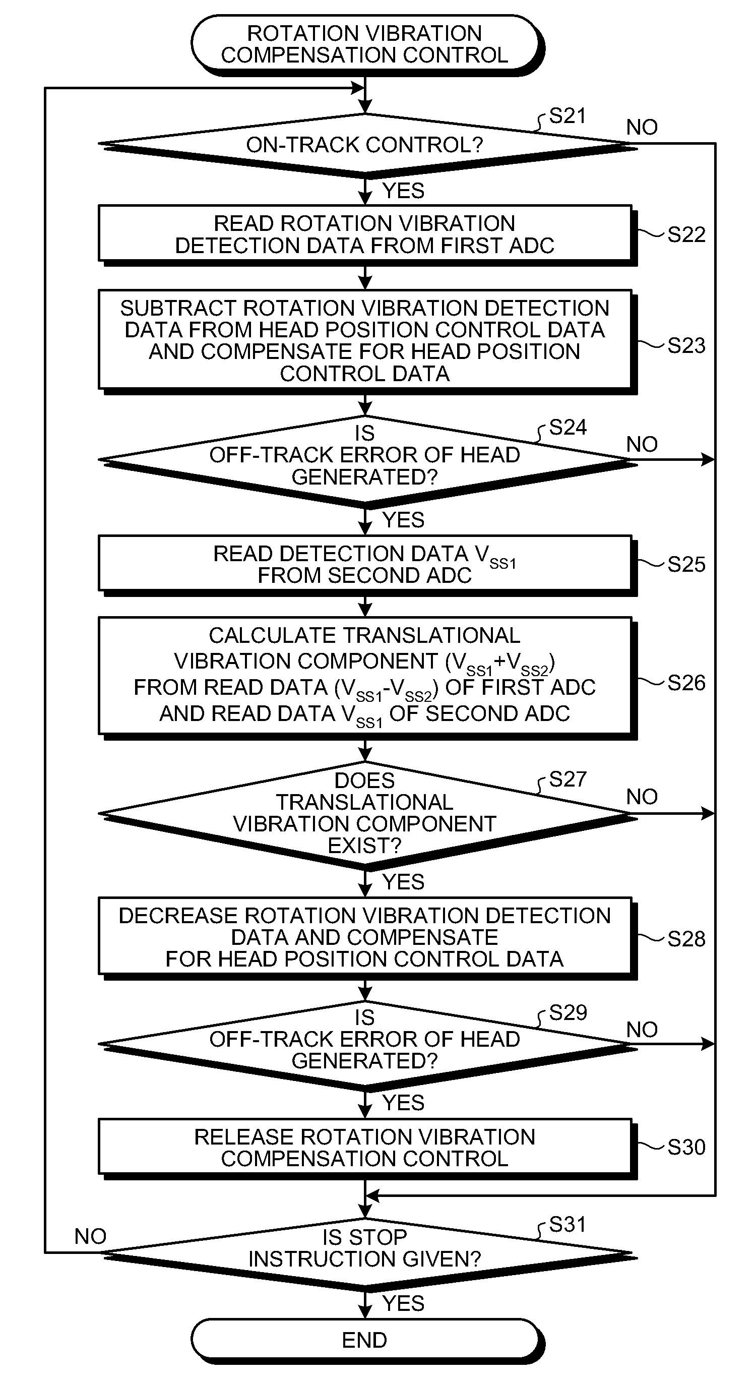
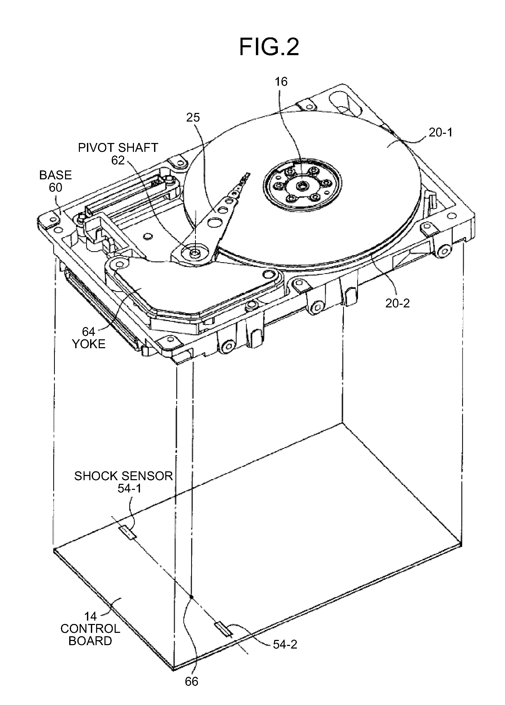
[0107]In the third embodiment, as illustrated in FIG. 2, the shock sensors 54-1 and 54-2 are arranged with the pivot shaft 62 being the rotation center of the rotary actuator 25 therebetween. The difference between the vibration detection signals is calculated, a signal component by the translational vibration applied to the entire device in one direction, i.e., the translational vibration detection signals having the same polarity generated in the shock sensors 54-1 and 54-2 are offset. The difference is calculated to extract rotation vibration detection signals that are signals having the reverse polarity generated in the shock sensors 54-1 and 54-2.

[0108]However, when the shock sensors 54-1 and 54-2 are arranged are unstable places on a printed board such as the control board 14, even in the translational vibration applied to the entire device, the rotation vibration component may be generated in the shock sensors 54-1 and 54-2.

[0109]In this case, even if the rotation vibration i...


PUM

PropertyMeasurementUnit
resistanceaaaaaaaaaa
distanceaaaaaaaaaa
rotationaaaaaaaaaa

Abstract

According to one embodiment, a storage device includes a rotary actuator, vibration detectors, an analog operation circuit, an analog-to-digital converter, and a rotation vibration compensation controller. The rotary actuator positions a head with respect to a storage medium to perform reading or writing. The vibration detectors are located substantially on both sides of the rotation center of the rotary actuator, detects rotation vibration component of a one-axis direction, and outputs a vibration detection signal. The analog operation circuit calculates a rotation vibration detection signal proportional to rotation vibration disturbance applied to the rotary actuator by differential amplification of the vibration detection signal. The analog-to-digital converter converts the rotation vibration detection signal into a digital signal and outputs rotation vibration detection data. The rotation vibration compensation controller controls the rotation vibration disturbance applied to the rotary actuator to be eliminated based on the rotation vibration detection data.

Description

CROSS-REFERENCE TO RELATED APPLICATIONS[0001]This application is a continuation of PCT international application Ser. No. PCT / JP2007 / 059657 filed on May 10, 2007 which designates the United States, incorporated herein by reference.BACKGROUND[0002]1. Field[0003]One embodiment of the invention relates to a storage device and a control circuit that position a head with respect to a storage medium by a rotary actuator.[0004]2. Description of the Related Art[0005]In general, when a magnetic disk device is mounted in a rack of a storage system, the magnetic disk device is affected by a vibration of a fan or another disk. This vibration physically vibrates a rotary actuator and appears as disturbance in a head position signal.[0006]As the vibration applied to the magnetic disk device, translational vibration and twisting vibration exist. The translational vibration causes the entire device to move in one direction, and does not affect positioning of the head because the rotary actuator int...

Claims


Application Information

Patent Timeline
Patent Type & Authority Applications(United States)
IPC IPC(8): G11B5/02
CPCG11B5/59627
Inventor MATSUSHITA, HIROKIHIGASHINO, YOSHINARI
Owner TOSHIBA STORAGE DEVICE CORP
Why Eureka
Try Eureka