Device and method for imaging skin objects, and a method and device for reducing hair growth by means thereof

a skin object and imaging technology, applied in the field of skin object imaging devices and methods, can solve the problems of significant reduction of e.g. shaving quality, significant affecting hair orientation, and affecting hair detection efficiency, and achieves small focal area, high power density, and high value for cutting hairs.

Inactive Publication Date: 2010-03-11
KONINKLIJKE PHILIPS ELECTRONICS NV
View PDF5 Cites 77 Cited by
  • Summary
  • Abstract
  • Description
  • Claims
  • Application Information

AI Technical Summary

Benefits of technology

[0031]In a special embodiment, the source comprises a laser, the device preferably further comprising a laser power control means that is arranged to switch an emitted laser power between two different non-zero values. A first value is e.g. a low value for imaging, and a second value is e.g. a high value for cutting hairs. A laser is a very suitable source of optical radiation since it is able to provide a high power density in a very small focal area, which is useful because there are high losses due to absorption and suppression of unwanted light. In various circumstances, focusing onto a small focal spot, roughly at most of the order of the diameter of the object to be imaged, is advantageous. In the case of hairs, a diameter of a few tens of micrometers is useful, although other diameters are not excluded. Such a diameter

Problems solved by technology

As a result thereof, hair orientation significantly affects hair detection efficiency, which in its turn significantly decreases e.g. shaving quality, in particular during ind

Method used


Image

  • Device and method for imaging skin objects, and a method and device for reducing hair growth by means thereof
  • Device and method for imaging skin objects, and a method and device for reducing hair growth by means thereof
  • Device and method for imaging skin objects, and a method and device for reducing hair growth by means thereof

Examples


Embodiment Construction

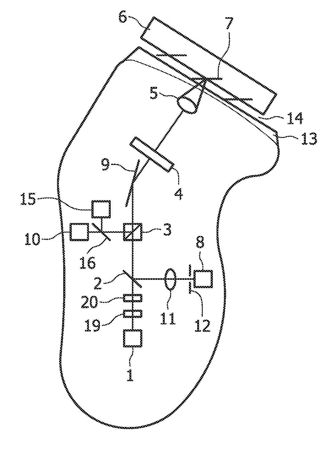
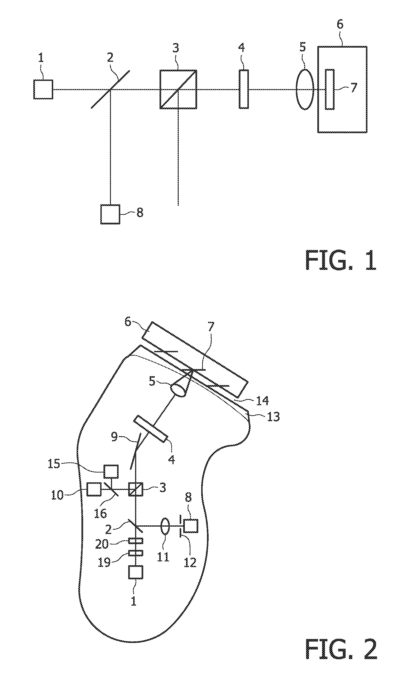
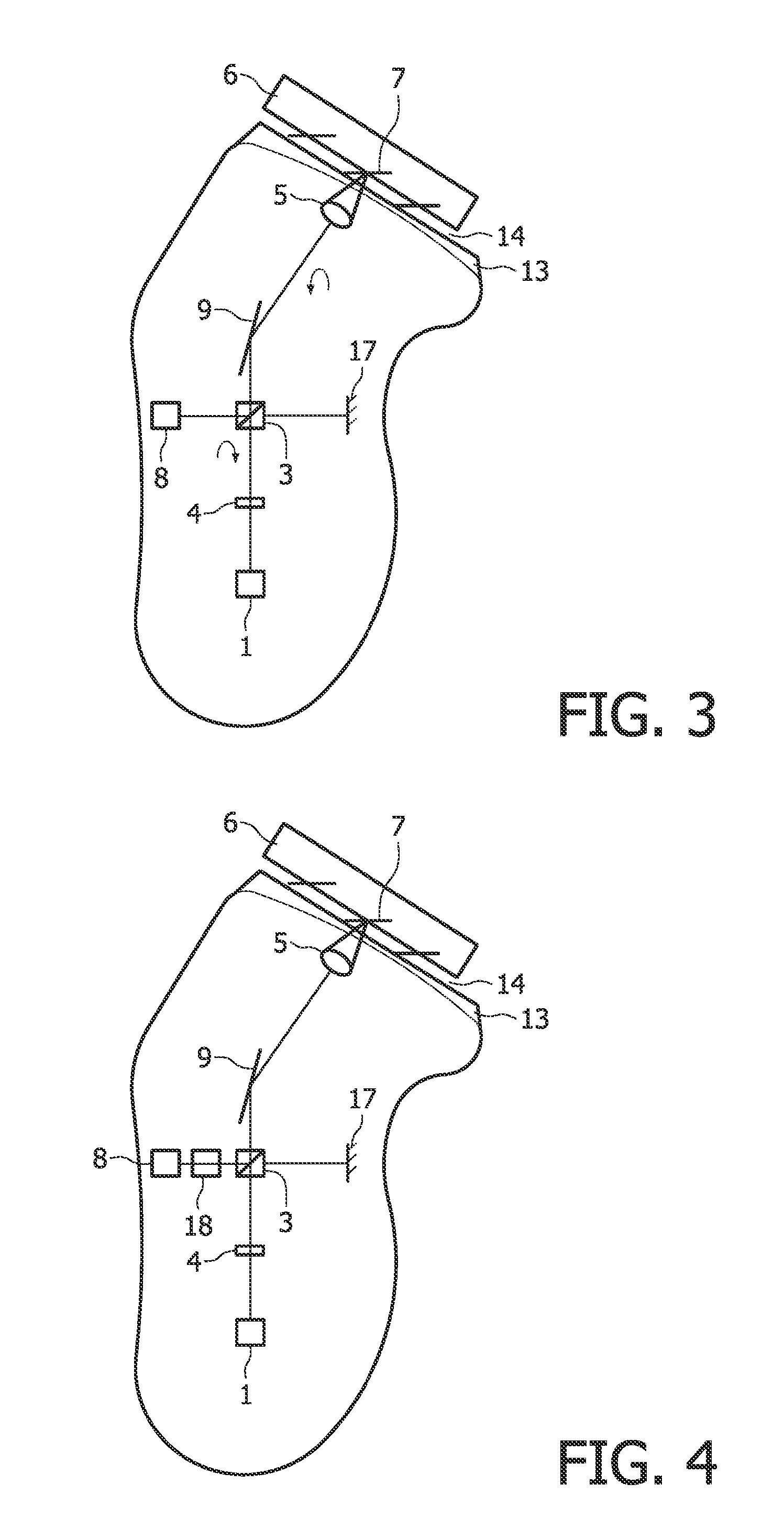
[0038]FIG. 1 shows a highly diagrammatic embodiment of the device according to invention. Herein, 1 is a light source for imaging, 2 denotes a beam splitter, 3 denotes a polarizing beam splitter, 4 denotes a quarter-wave plate, 5 denotes an imaging lens, 6 denotes tissue, 7 denotes a hair, and 8 denotes a detector.

[0039]The light source 1, such as a LED, but preferably a laser, emitting near infrared radiation of a wavelength of e.g. 834 or 1310 nm, emits with a linear polarization, e.g. in a p-state. If necessary, a linear polarizer may be added. The beam passes the beam splitter 2 and the polarizing beam splitter 3. Next, the beam passes a quarter-wave plate 4 and becomes circularly polarized, at least if the electric field factor of the beam is oriented at an angle of 45° to the fast axis of the plate 4. Next, the beam passes the imaging lens 5 and enters the tissue 6, such as skin. On entering, a major portion of the radiation will be reflected. The portion that enters the tissu...


PUM


Abstract

There is provided a device for imaging a skin object (7) near a skin surface of a body part, comprising a light source (1) and a detector (8) for detecting radiation returning from said object (7), wherein the device further comprises an elliptical, preferably circular, polarizer (4, 19) between the source (1) and said skin (6) surface, the device comprising a 5 ratio increaser means (3, 4, 19) for increasing the ratio of radiation from said object (7) to radiation from said skin (6) surface. The ratio increaser may be an additional or the same elliptical polarizer. Using elliptically or even circularly polarized light makes hair detection independent of the orientation of hair (7) with respect to light or polarization, which renders 10 the detection more reliable. The invention also provides an imaging method and a hair-shortening device and method.

Description

FIELD OF THE INVENTION[0001]The present invention relates to a device and method for imaging a skin object, such as objects on or beneath a skin surface of a body part, and to a method and device for reducing hair growth by means of said device and method.[0002]In particular, the present invention relates in a first aspect to a device for imaging a skin object near a skin surface of a body part, comprising a source arranged to emit optical radiation having a wavelength between 600 and 2000 nm and a detector arranged to detect optical radiation returning from said object.BACKGROUND OF THE INVENTION[0003]Document WO / 2005 / 102153 dicloses a hair detection device with a source of electromagnetic radiation and an imaging sensor, and with radiation selection means. The device couples the radiation into the skin, and said radiation reaches the sensor after multiple scattering. The radiation selection means improves a ratio between said multiply scattered radiation and other, unwanted radiat...

Claims


Application Information

Patent Timeline
IPC IPC(8): A61B18/20A61B6/00
CPCA61B5/0066A61B5/0068A61B5/1072A61B5/417A61B5/441A61B2018/00904A61B18/20A61B18/203A61B2018/00452A61B2018/00476A61B5/448
Inventor VERHAGEN, RIEKOSPIKKER, BART WILLEM JANVAN HAL, ROBBERT ADRIANUS MARIAKHARIN, ALEKSEYUZUNBAJAKAVA, NATALLIA
Owner KONINKLIJKE PHILIPS ELECTRONICS NV
Why Eureka
Try Eureka