Data center

Inactive Publication Date: 2010-03-18
HITACHI CABLE
View PDF15 Cites 71 Cited by
  • Summary
  • Abstract
  • Description
  • Claims
  • Application Information

AI Technical Summary

Benefits of technology

[0012]Therefore, it is an object of the invention to provide a data center that reduces energy consumption in an air-conditioned room by efficiently eliminating heat generated from the electronic device in the rack, and to effectively use heat concentrated in a hot zone defined therein.
[0016]an air conditioner for conditioning air in the air-conditioned room to eliminate heat generated from the electronic devices housed in the plurality of racks; and
[0035]According to one embodiment of the invention, a data center is constructed such that a hot zone is defined by a floor surface, two rack rows arranged on the floor surface of the air-conditioned room such that rear sides thereof are opposite each other at a distance, a ceiling disposed above the two rack rows, two panels disposed at both ends of the two rack rows in the horizontal direction and extending from a lower end of the two rack rows to the ceiling, and two partitions disposed at a front top end of the two rack rows and extending to the ceiling. Thus, heat discharged from the top of the rack can be discharged not into the air-conditioned room but into the hot zone so that all of heat generated from the electronic device can be concentrated in the hot zone and the air conditioner can be efficiently operated.
[0036]Further, in the embodiment, heat of the air discharged through an exhaust port is recovered by a heat recovery means before cooling down the air by the dry coil, thus, it is possible to effectively use heat concentrated in the hot zone without diffusion.
[0037]In addition, unlike the conventional data center, the rack rows are completely separated from the air conditioner (i.e., not connected thereto by pipes etc.) or the hot zone and the rack rows are mounted on a seismic isolator, so that, even when a strong earthquake breaks out, there will be no risk that coolant, chlorofluorocarbon etc. leaks out due to breakage of the pipes for coolant, etc., or that the electronic device is damaged due to water falling on the rack row.

Problems solved by technology

Under these circumstances, energy consumed in the air conditioner (the indoor air conditioner) is wasted, thus, there is a problem from the viewpoint of energy saving.
Since there is a type of server which exhausts the air upwards, when such a server is housed in the rack 71, a large amount of heat is discharged from the upper surface of the rack 71 into the air-conditioned room, thus, the above-mentioned problem remarkably occurs.

Method used


Image

  • Data center
  • Data center
  • Data center

Examples


embodiments

[0046]Preferred embodiments according to the invention will be explained as below in conjunction with appended drawings.

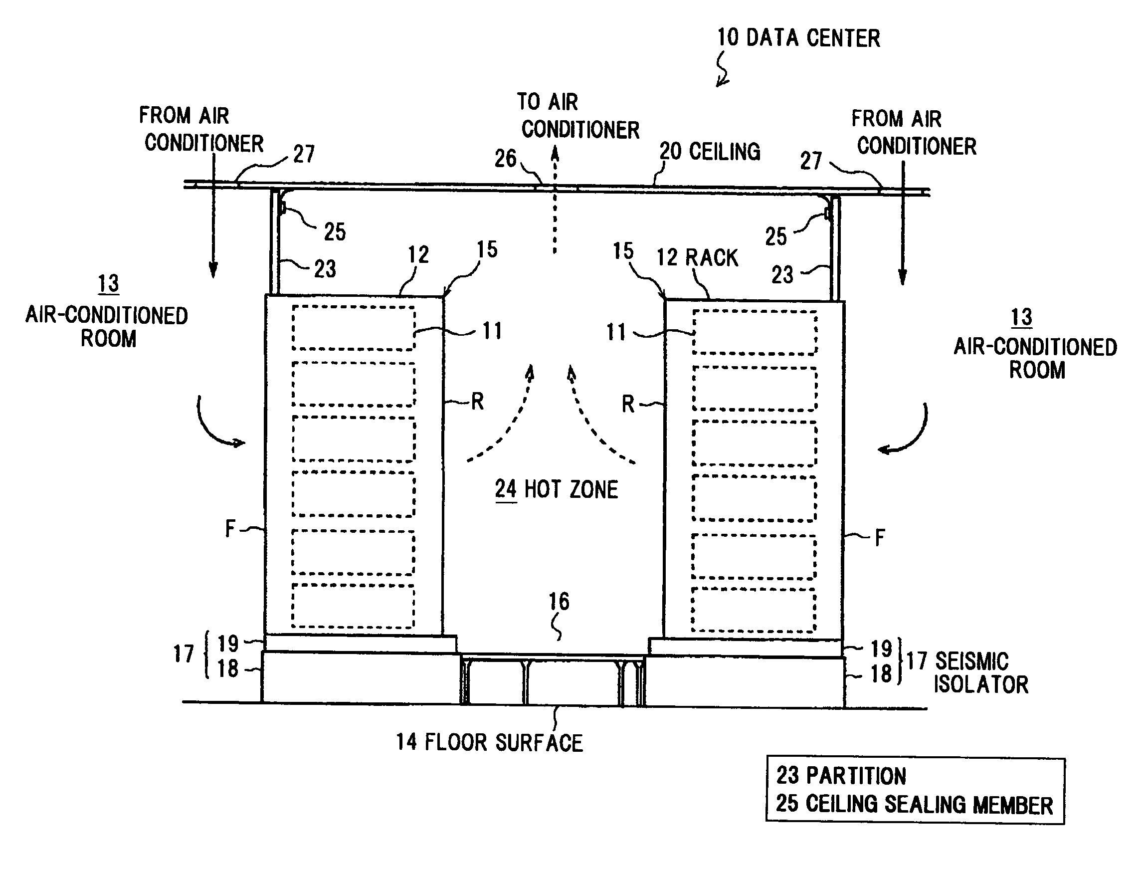
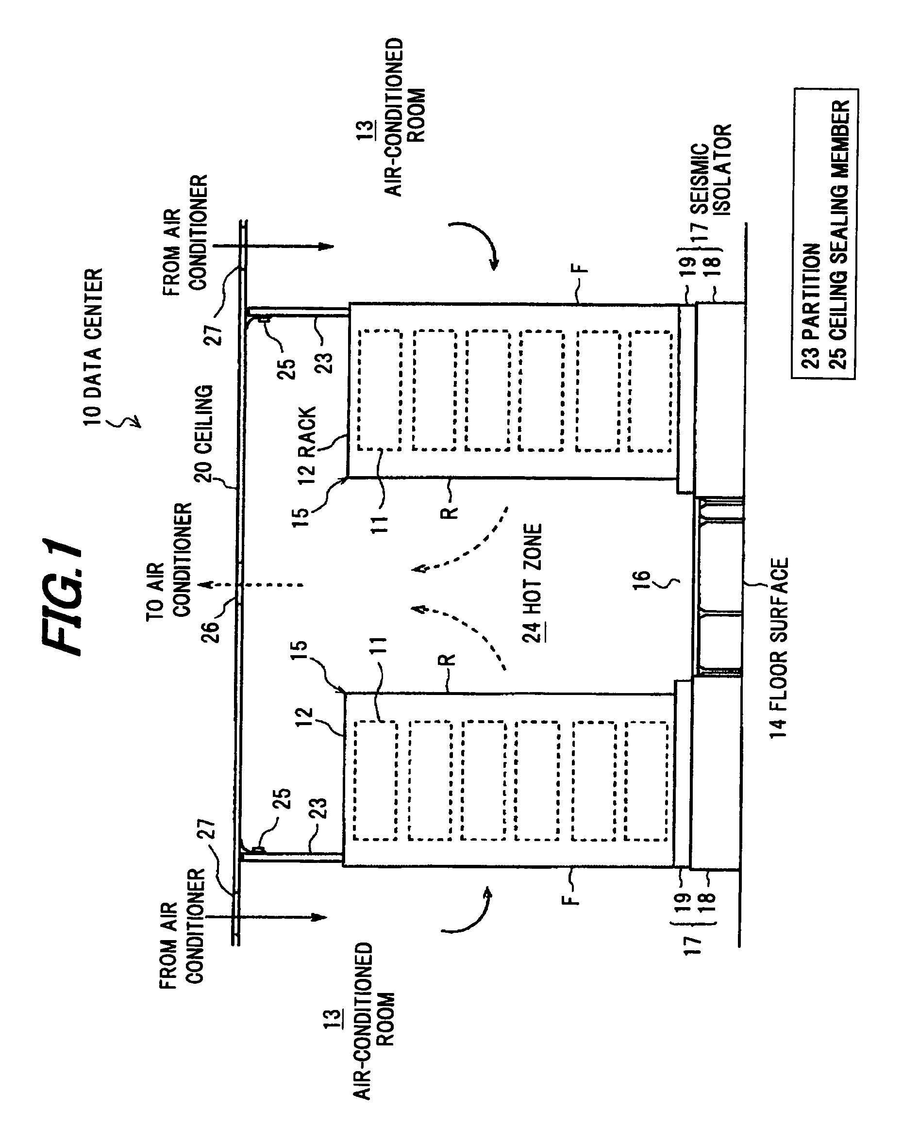
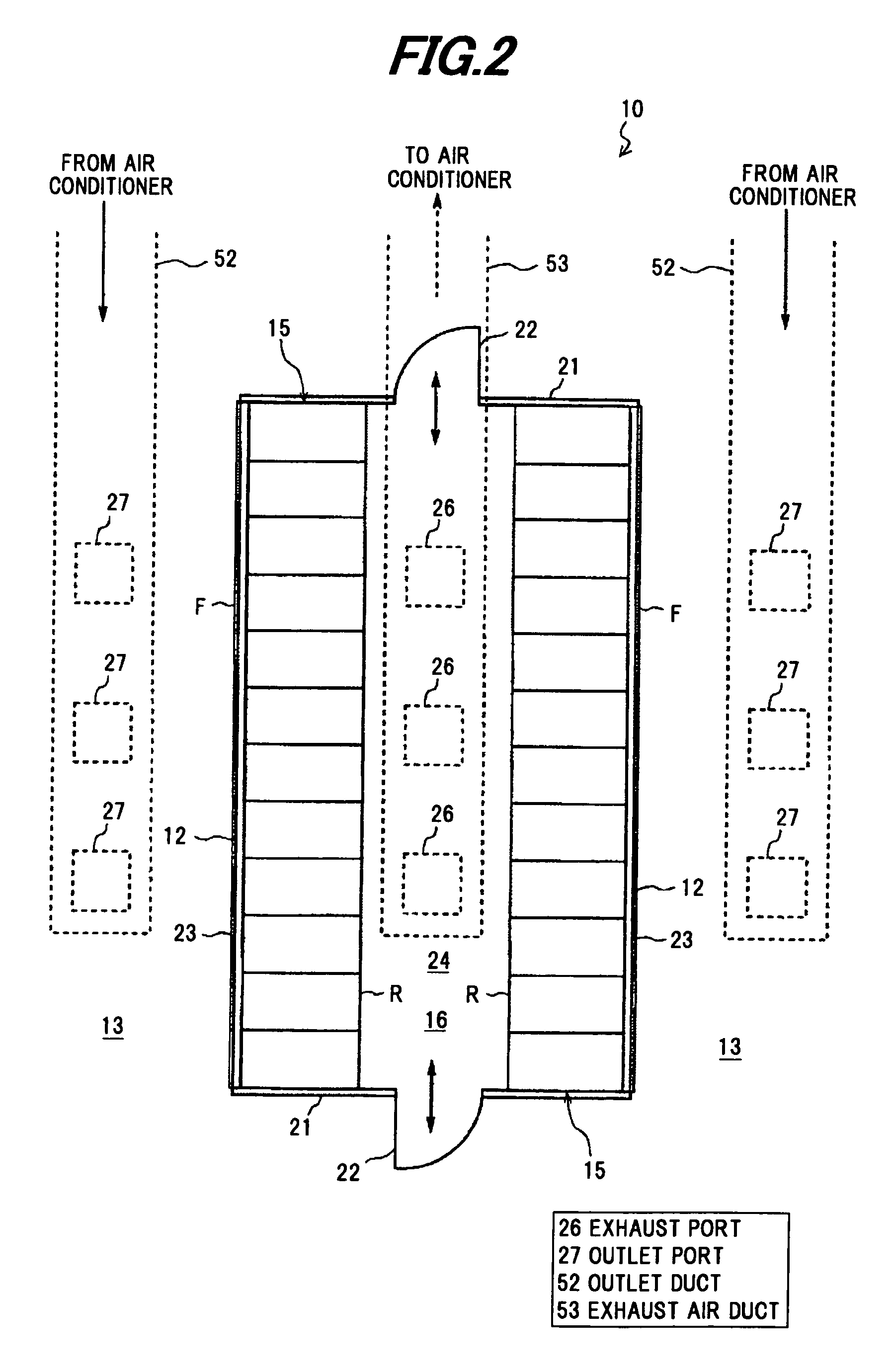
[0047]FIG. 1 is a schematic cross sectional view showing a data center in the preferred embodiment, FIG. 2 is a plan view thereof, FIG. 3 is a side view thereof, and FIG. 4 is a front view thereof.

[0048]As shown in FIGS. 1 to 4, a data center 10 includes at least a box-shaped air-conditioned room 13 composed of a ceiling, a floor surface and four side walls, a rack row 15 formed by horizontally aligning plural racks 12 housing electronic devices 11 such as a sever, etc., in multi-tiers, and an air conditioner (not shown) for conditioning air inside the air-conditioned room 13 in order to remove heat generated in the electronic device 11 which is housed in the rack 12.

[0049]The electronic devices 11, which are equipments for information and communication technology such as a server, a CPU, a network equipment or a storage device, are housed in the racks 12 in multi-...


PUM


Abstract

A data center includes an air-conditioned room, two rack rows formed on a floor surface of the air-conditioned room and each composed of a plurality of racks arranged in a horizontal direction, each of the plurality of racks housing electronic devices in multistage configuration, an air conditioner for conditioning air in the air-conditioned room to eliminate heat generated from the electronic devices housed in the plurality of racks, and a hot zone in the air-conditioned room. The hot zone is defined by the two rack rows arranged on the floor surface of the air-conditioned room such that rear sides thereof are opposite each other at a distance, a ceiling disposed above the two rack rows, two panels disposed at both ends of the two rack rows in the horizontal direction and extending from a lower end of the two rack rows to the ceiling, and two partitions disposed at an upper front top end of the two rack rows and extending to the ceiling. The ceiling includes an exhaust port for discharging heat in the hot zone, and the air conditioner is operable to introduce air-conditioned air from the air-conditioned room through front sides and then the rear sides of the two rack rows into the hot zone. The data center further includes a heat recovery means for recovering a heat of the air discharged through the exhaust port from the hot zone before cooling down the air by the air conditioner.

Description

[0001]The present application is based on Japanese Patent Application No. 2008-236437 filed on Sep. 16, 2008, the entire contents of which are incorporated herein by reference.BACKGROUND OF THE INVENTION[0002]1. Field of the Invention[0003]The invention relates to a data center that heat generated from an electronic device such as a server housed in a rack can be efficiently eliminated.[0004]2. Related Art[0005]In general, electronic devices such as a server, etc., are housed in racks with high density in multi-tiers, and are arranged in an air-conditioned room. Since heat is generated in the electronic device in accordance with power consumption, air-conditioned air (cool air) is generally supplied to the electronic device housed in the rack by a cooling system such as an air conditioner for removing the heat generated in the electronic device in order to eliminate an adverse effect due to the heat.[0006]As shown in FIG. 7, a conventional data center is entirely configured by provi...

Claims


Application Information

Patent Timeline
IPC IPC(8): F25D23/00F25D23/12F24F11/053F24F12/00F24F13/02F24F11/76
CPCH05K7/20745
Inventor TASHIRO, KANJI
Owner HITACHI CABLE
Why Eureka
Try Eureka