

Ice machines with extruded heat exchanger
- Summary
- Abstract
- Description
- Claims
- Application Information
AI Technical Summary
Benefits of technology
Problems solved by technology
Method used
Image

Examples
Embodiment Construction
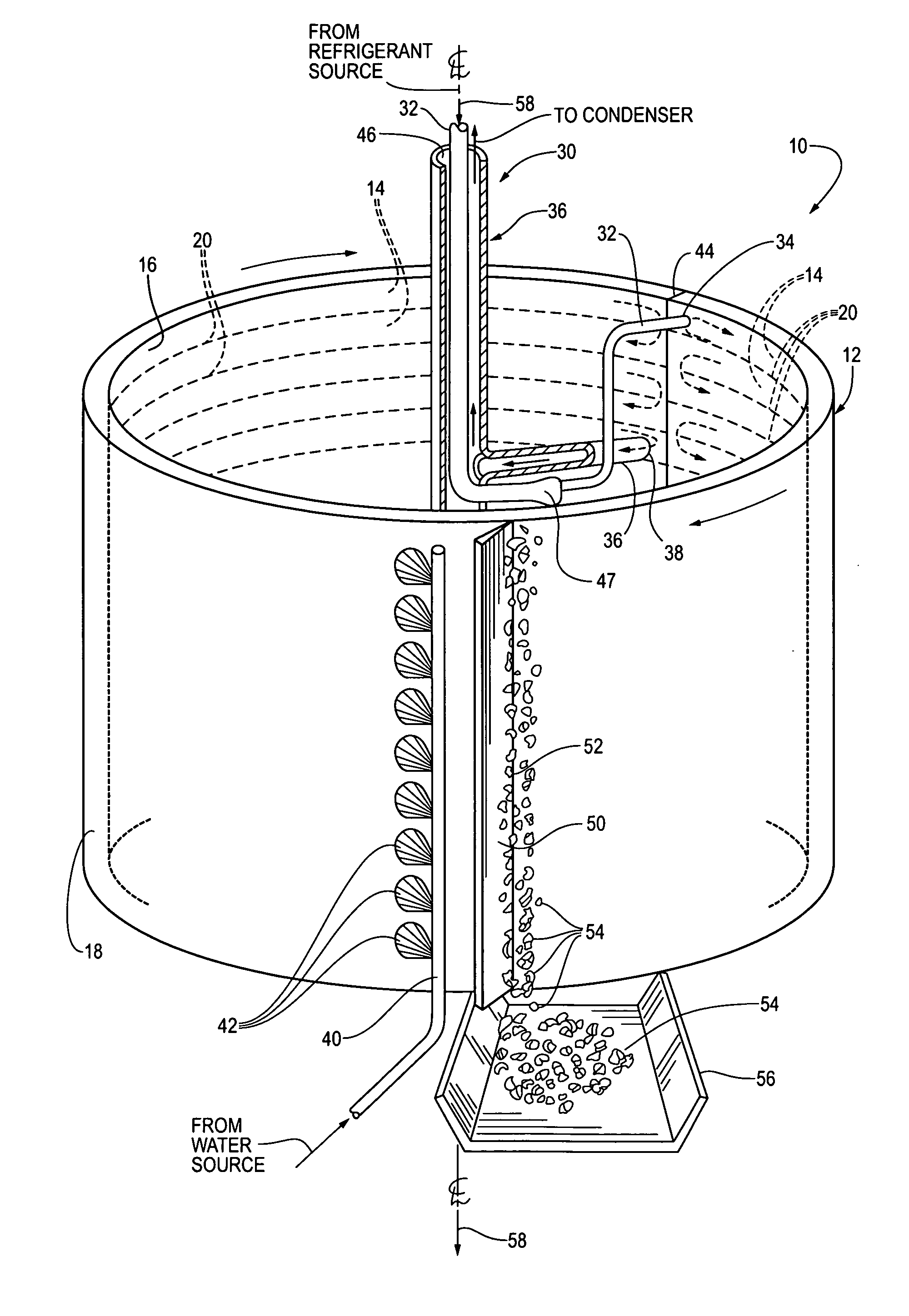
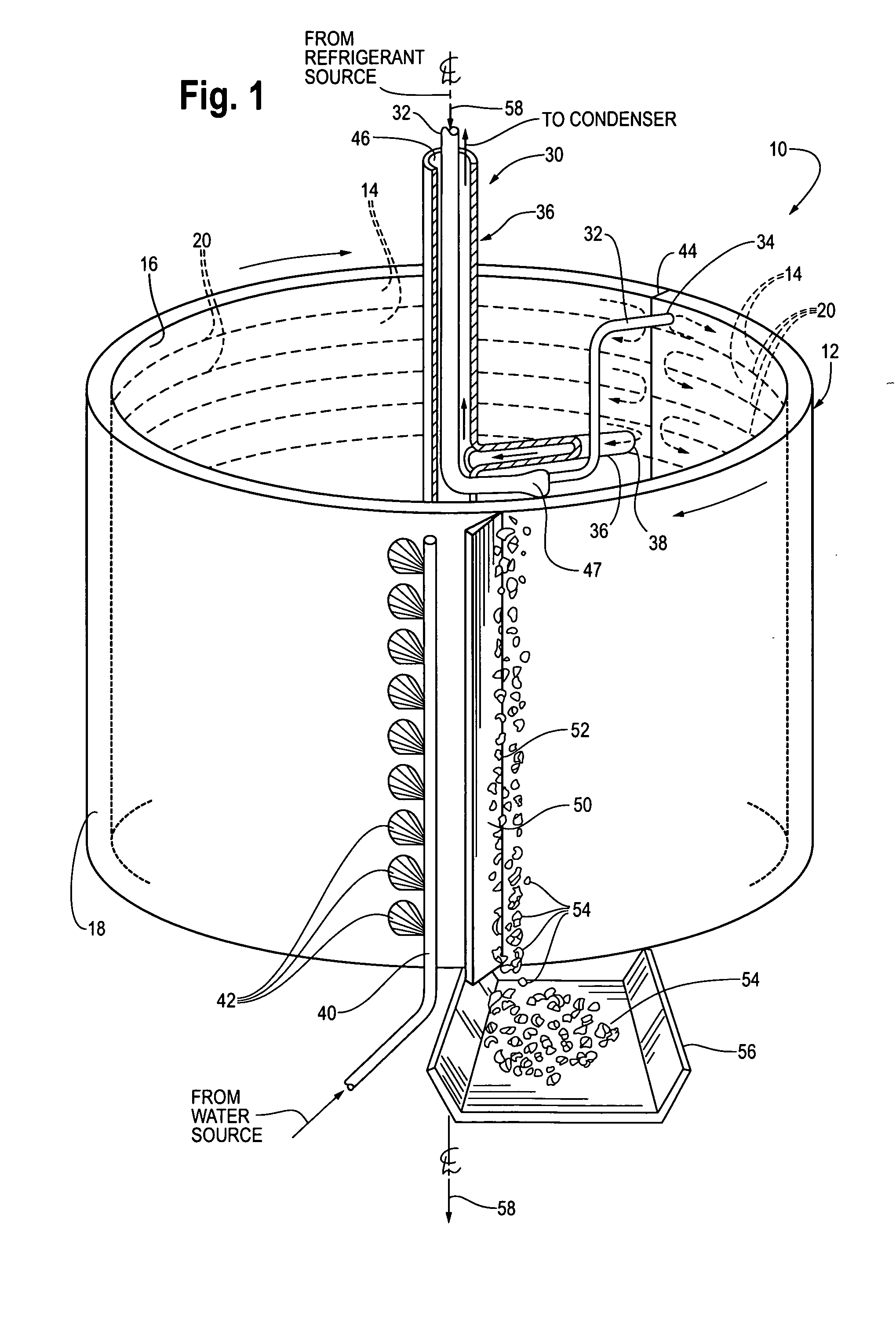
[0050]Referring now to the drawings, FIG. 1 is perspective view of an ice machine 10 according to one embodiment of this invention. The ice machine 10 can be used for making flake or slurry forms of ice.
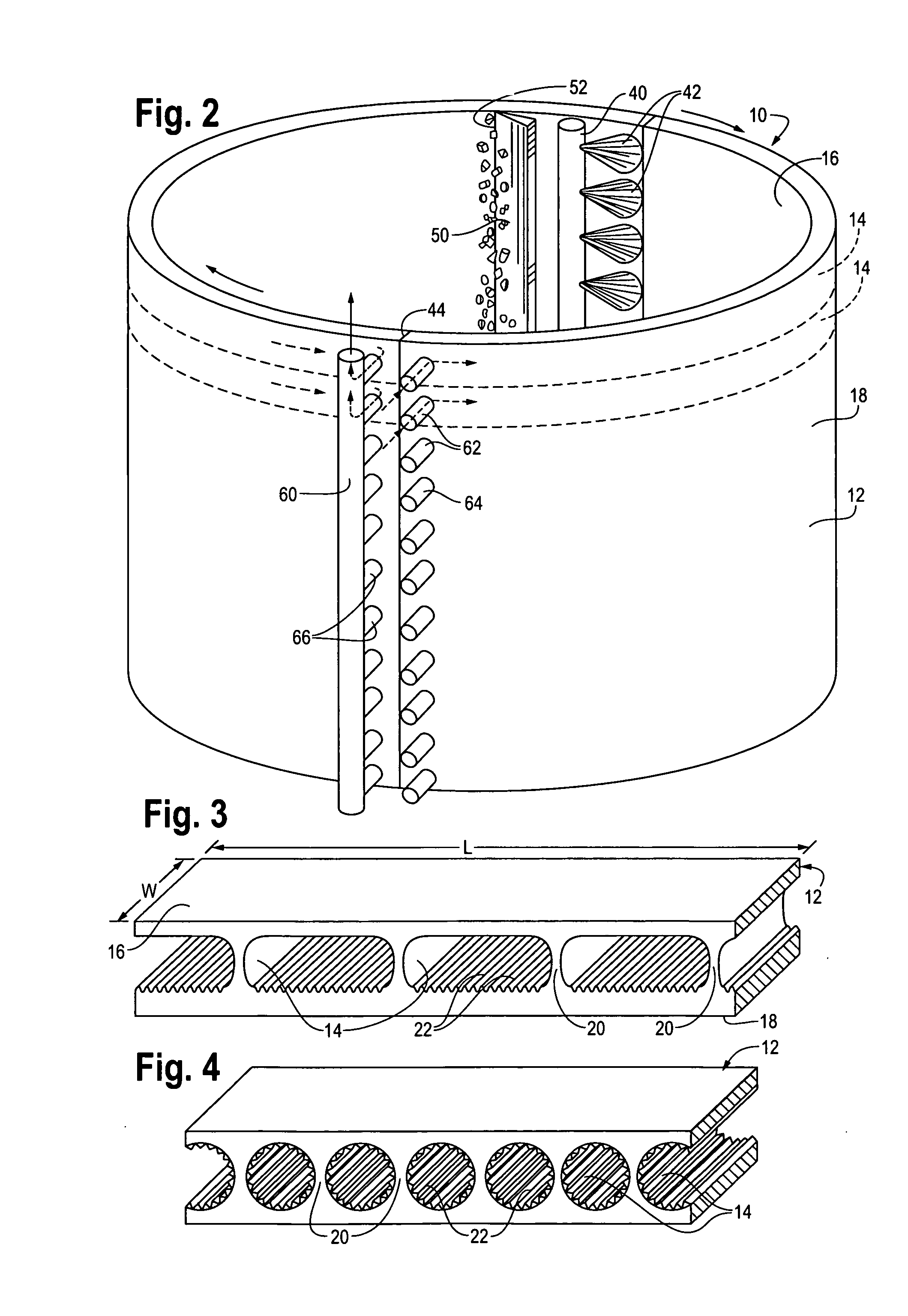
[0051]The ice machine includes a cylindrical heat exchanger 12 in the form of a drum. The heat exchanger 12 includes inner and outer cylindrical walls 16 and 18, respectively. Refrigeration passages 14 shown in dashed lines are provided between the walls 16 and 18 for flow of a refrigerant. The inner and outer walls 16 and 18 are separated from each other by wall or web-like connecting structures 20 which define the refrigeration passages 14. These connecting structures 20 are best shown in FIGS. 3 and 4 and will be described below. The refrigeration passages 14 optionally include a multitude of raised and recessed features 22 (see FIGS. 3, 4) such as corrugations or other type of surface increasing the surface area of the refrigeration passages 14 thereby enhancing the heat transfer...
PUM
| Property | Measurement | Unit |
|---|---|---|
| Length | aaaaa | aaaaa |
| Flow rate | aaaaa | aaaaa |
| Surface area | aaaaa | aaaaa |
Abstract
Description
Claims
Application Information