Blenders

a technology of cleaning brushes and cleaning brushes, applied in the field of cleaning brushes, can solve the problems of low bulk density materials, blenders are often in somewhat inaccessible and elevated locations, cleaning can present a safety hazard to workers,

Inactive Publication Date: 2010-03-18
VERVANT
View PDF18 Cites 14 Cited by
  • Summary
  • Abstract
  • Description
  • Claims
  • Application Information

AI Technical Summary

Benefits of technology

[0028]In another embodiment each material supply bin has a pressurised air supply connected to it which may be actuated via a control m

Problems solved by technology

A problem can arise in handling low bulk density materials such as regrind flake in accurately mixing and feeding material mixtures containing such low bulk density materials.
However, these blenders are often in somewhat inaccessible and elevated locations.
Thus, cleaning can present a safety

Method used


Image

  • Blenders
  • Blenders
  • Blenders

Examples


Embodiment Construction

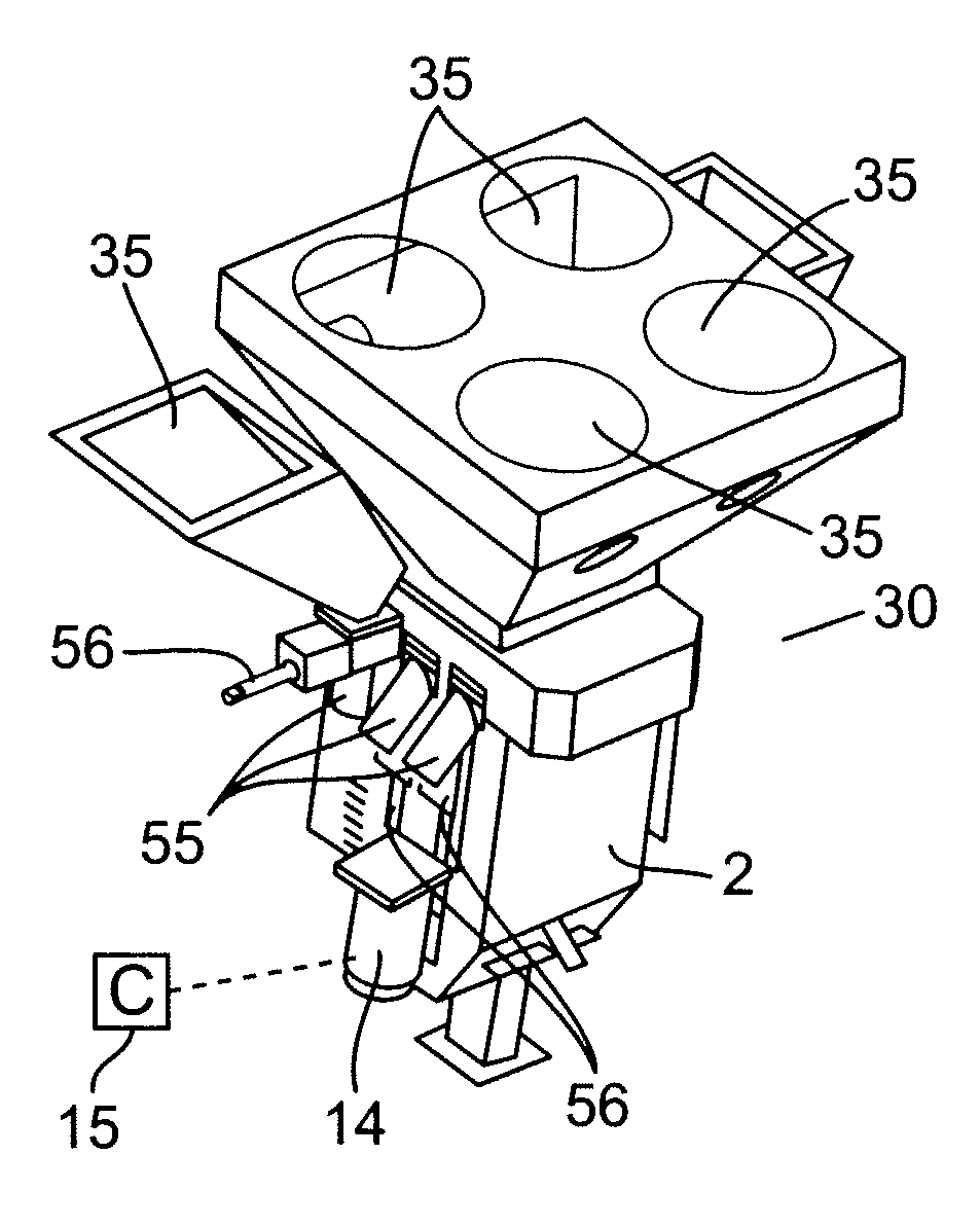
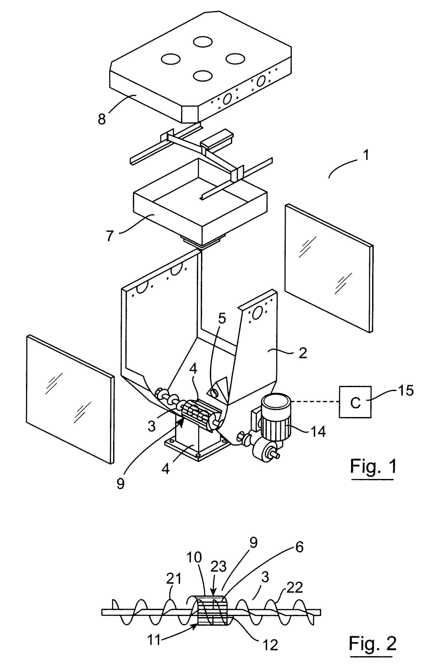
[0062]Referring to the drawings, and initially to FIGS. 1 and 2 thereof, there is illustrated a blender according to the invention indicated generally by the reference numeral 1. The blender 1 is largely similar to our blender described in European Patent Specification No. 0 911 130. The blender 1 has a mixing chamber 2 for reception of materials to be blended. A mixing screw 3 is mounted at a bottom of the mixing chamber 2 adjacent an outlet 4 of the mixing chamber 2 for circulation and mixing of materials within the mixing chamber 2 prior to discharge through the outlet 4. A material level sensor 5 is mounted within the chamber 2 above the screw 3. The level sensor 5 is connected to a controller 15 which is operable to regulate the supply of fresh materials from a weigh hopper 7 to the mixing chamber 2 for mixing. A number of raw material supply bins (not shown) are mounted above a support platform 8 located above the weigh hopper 7 for feeding selected raw material ingredients to...


PUM

PropertyMeasurementUnit
Mixtureaaaaaaaaaa

Abstract

A blender has a mixing chamber for reception of materials to be blended. A mixing screw is mounted at a bottom of the mixing chamber for mixing materials within the mixing chamber and delivering mixed materials to an outlet feeding a processing line. A baffle is mounted at the outlet extending about the mixing screw. The baffle inhibits upward movement of material at the outlet tending to cram material into the outlet.

Description

INTORDUCTION[0001]This invention relates to blenders for various processes but may also be used in other applications.[0002]The invention particularly relates to blenders for the controlled mixing and delivery of particulate blend additives into a material processing line, for extruding plastics material for example. Examples of such blenders are to be found in our previous patent no's: U.S. Pat. No. 6,155,709 and U.S. Pat. No. 6,203,184. A problem can arise in handling low bulk density materials such as regrind flake in accurately mixing and feeding material mixtures containing such low bulk density materials. Further, such blenders are commonly used for batch production processes. It is therefore necessary to regularly clean out all the raw materials from a current batch production before setting up the blender for a new batch production run for another product. This is typically done manually. However, these blenders are often in somewhat inaccessible and elevated locations. Thus...

Claims


Application Information

Patent Timeline
IPC IPC(8): B65B1/04B01F15/02B01F15/00B01F15/06
CPCB01F3/12B29B7/22B01F5/248B01F7/007B01F7/088B01F13/1005B01F15/00123B01F15/00155B01F15/00207B01F15/0024B01F15/0267B01F15/0287B01F15/0445B01F15/0483B01F15/067B01F2215/0049B29B7/14B29B7/88B65G65/46B01F3/184B01F23/64B01F23/50B01F25/85B01F27/2122B01F27/726B01F33/8051B01F35/2112B01F35/20B01F35/213B01F35/2135B01F35/751B01F35/7545B01F35/892B01F35/94B01F35/881B01F2101/2805F26B2200/08F26B2200/14F26B2200/00B01F27/1143B01F35/10B01F35/93B01F35/145B01F35/1452B01F35/1453B01F35/2117B01F35/7543B01F35/7547B01F35/71731B01F2035/99B29B13/065F26B3/06F26B25/22
Inventor O'CALLAGHAN, JAMES JOSEPH
Owner VERVANT
Why Eureka
Try Eureka