
Plasma generating apparatus

Inactive Publication Date: 2010-03-18
SAMSUNG ELECTRONICS CO LTD
View PDF2 Cites 42 Cited by
  • Summary
  • Abstract
  • Description
  • Claims
  • Application Information

AI Technical Summary

Benefits of technology

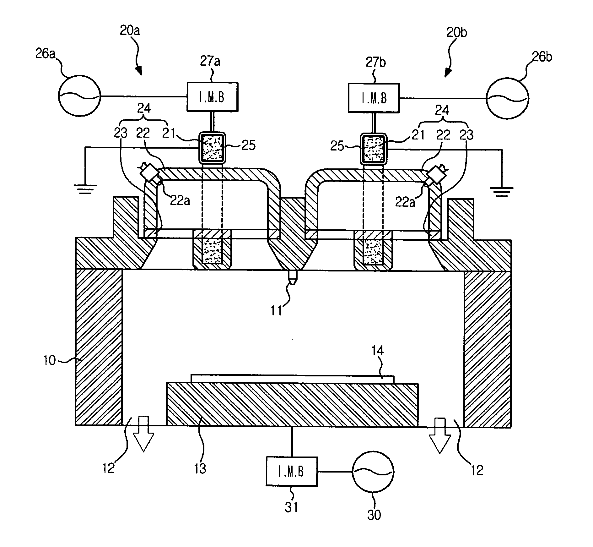
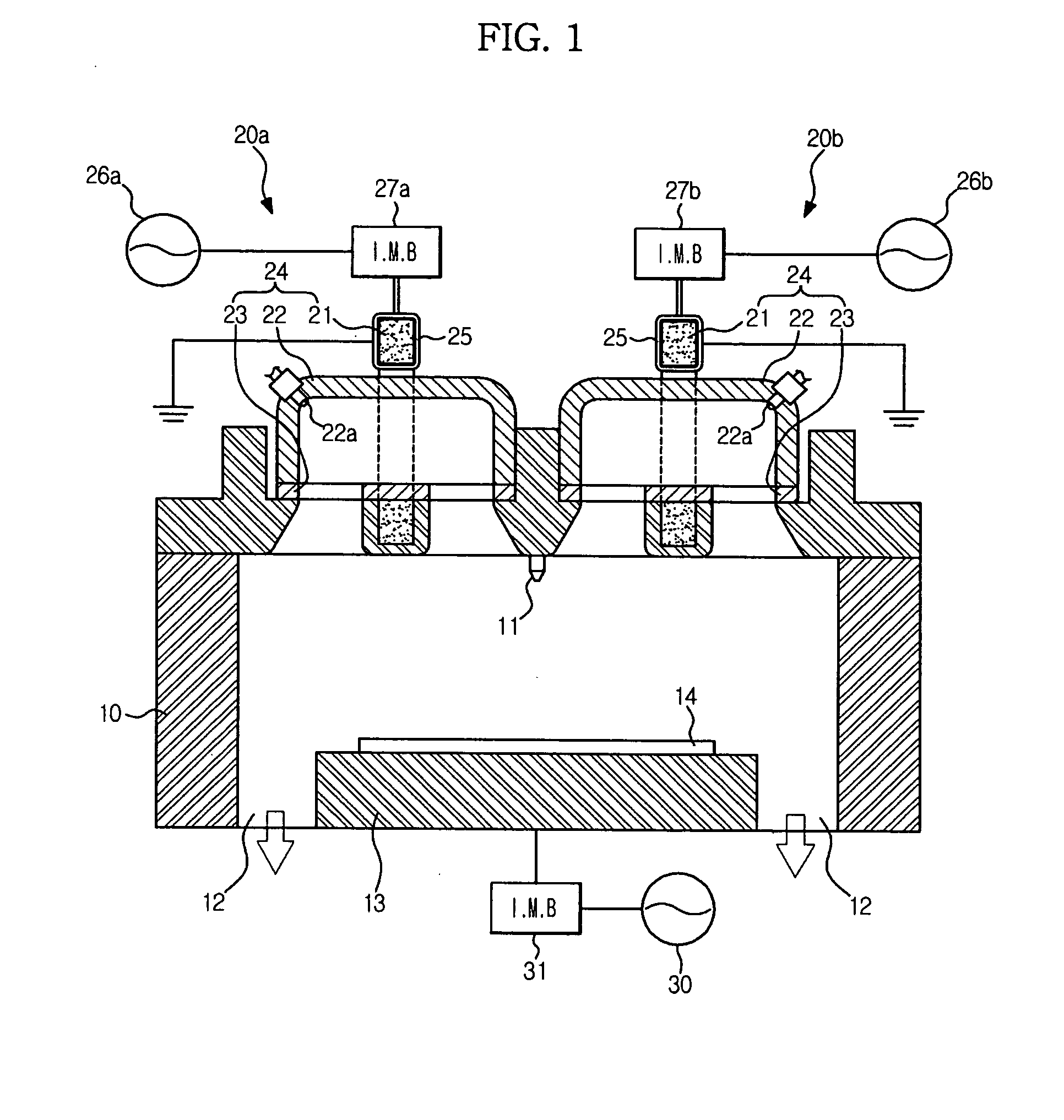
[0015]The plasma channel may have an inverted U-shaped form to reduce the loss of plasma.
[0022]The ferrite core may have a closed-looped shaped form and is disposed perpendicular to an upper surface of the reactor chamber, and the plasma channel may have an inverted U-shaped form to reduce the loss of plasma. As shown in FIG. 5, the ferrite core may be square form. When the plasma channel is a metal tube, a DC brake to prevent current from being induced to the plasma channel may be further provided.
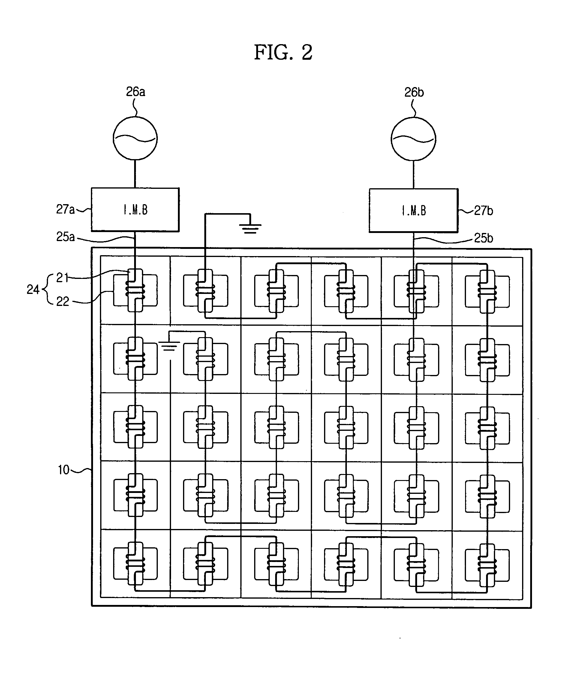
[0025]In a plasma generating apparatus in accordance with any aspect of the general inventive concept as described above, with the presence of a ferrite core having high magnetic permeability and a plurality of plasma source modules each having a plasma channel through which plasma passes, large-area and high-density plasma may be effectively generated and uniformly distributed without configuration of a dielectric window.

Problems solved by technology

Although conventional ICP generating apparatuses are used in the semiconductor field, the conventional ICP generating apparatuses have a limit in the generation of large-area and high-density plasma.

Method used


Image

  • Plasma generating apparatus
  • Plasma generating apparatus
  • Plasma generating apparatus

Examples


Embodiment Construction

[0034]Example embodiments of the present invention will now be described more fully with reference to the accompanying drawings, in which the example embodiments are shown. The invention may, however, be embodied in different forms and should not be construed as limited to the embodiments set forth herein. Rather, these embodiments are provided so that this disclosure will be thorough and complete, and will fully convey the scope of the invention to those skilled in the art. In the drawings, the sizes of components may be exaggerated for clarity.

[0035]It will be understood that when an element or layer is referred to as being “on”, “connected to”, or “coupled to” another element or layer, it can be directly on, connected to, or coupled to the other element or layer or intervening elements or layers that may be present. In contrast, when an element is referred to as being “directly on”, “directly connected to”, or “directly coupled to” another element or layer, there are no interveni...


PUM

PropertyMeasurementUnit
Densityaaaaaaaaaa
Currentaaaaaaaaaa
Plasma poweraaaaaaaaaa

Abstract

A plasma generating apparatus including a plurality of plasma source modules. Each plasma source module includes a ferrite core having high magnetic permeability and a plasma channel through which plasma may pass. The plasma generating apparatus may effectively generate and uniformly distribute large-area and high-density plasma without a dielectric window.

Description

CROSS-REFERENCE TO RELATED APPLICATION(S)[0001]This application claims priority under 35 U.S.C. §119 to Korean Patent Application No. 10-2008-0090872, filed Sep. 17, 2008 in the Korean Intellectual Property Office (KIPO), the entire contents of which is incorporated herein by reference.BACKGROUND[0002]1. Field[0003]The general inventive concept relates to a plasma generating apparatus, and, more particularly, to a plasma generating apparatus that may be capable of improving plasma generating efficiency using a ferrite core.[0004]2. Description of the Related Art[0005]Plasma is an ionized gas that may consist of cations, anions, electrons, excited atoms, molecules, and / or highly chemically active radicals. Plasma is called “the fourth state of matter” because plasma has different electrical and thermal properties from normal gases. Plasma may cause acceleration of chemical reactions of an ionized gas by use of an electric and / or magnetic field and has been valuably utilized in fabric...

Claims


Application Information

Patent Timeline
IPC IPC(8): C23C16/513H01L21/3065
CPCH01J37/32357H01J37/321H01J37/3211H01J37/3244H01J37/32174H01J37/32715
Inventor JEON, SANG JEANTOLMACHEV, YURIPASHKOVSKIY, VASILYPARK, KEE SOOLEE, JU HYUNLEE, SU HOLEE, CHAN YUN
Owner SAMSUNG ELECTRONICS CO LTD
Learn More