Device and method for cutting off substrate of fragile material

a cutting device and a technology for fragile materials, applied in the direction of conveyors, paper/cardboard containers, box making operations, etc., can solve the problems of brittle material dust generation, broken pieces or the like of brittle material, and difficulty in holding the separated side edge portion with the table described above, so as to prevent the cutting of the face and prevent the production of brittle material.

Inactive Publication Date: 2010-03-18
MITSUBOSHI DIAMOND IND CO LTD
View PDF16 Cites 13 Cited by
  • Summary
  • Abstract
  • Description
  • Claims
  • Application Information

AI Technical Summary

Benefits of technology

[0016]As described above, the contact of the cut faces B1 and B2 to each other in the breaking step becomes a cause of impairing the quality of the substrate to be produced, and contaminating the substrate with generated dust and broken piece of the substrate material. As a result, this becomes a cause of reducing a yield of product and increasing a manufacturing cost, and this also becomes a cause of increasing a facility cost due to the requirement of extra facility such as substrate cleaning apparatus.
[0017]The objective of the present invention is to provide: a brittle material substrate cutting method for preventing a contact of cut faces after the cutting in a break step of continuously cutting a brittle material substrate along a scribe line so as to prevent a surface defect (e.g., scratch, chipping or the like) on the cut faces and to prevent the brittle material substrate from being contaminated with dust, a broken piece of the brittle material; and a brittle material substrate cutting apparatus used for implementing the brittle material substrate cutting method.
[0035]A brittle material substrate cutting apparatus according to the present invention is a brittle material substrate cutting apparatus for moving parts to be pressed along a scribe line formed on a brittle material substrate beforehand and continuously cutting the brittle material substrate. The brittle material substrate cutting apparatus according to the present invention includes a cut-face separating section for separating cut faces of two newly-formed substrate portions after the cutting. Therefore, it is possible to prevent the cut faces from contacting each other, so that a surface defect (e.g., scratch, chipping or the like) on the cut faces is prevented and a brittle material product is also prevented from being contaminated with dust, a broken piece of the brittle material.
[0036]Further, the cut-face separating section moves one of the cut substrate portions in either an upper direction or a lower direction while the cut faces are separated from each other, so that it is possible to prevent the cut faces from contacting each other in an assured manner after the cut faces are separated.

Problems solved by technology

As such, due to the pressing, friction or the like of the cut faces B1 and B2 to each other, a surface defect (e.g., scratch, chipping or the like) occurs on the cut faces B1 and B2, thus resulting in the generation of dust, a broken piece or the like of the brittle material.
In this case, when the width of the side edge portion to be separated is small, it is difficult to hold the separated side edge portion with the table described above or the like.
In such a case, a substrate portion to become a product is held by a suctioning table or the like while the side edge portion to be separated is not held at all, thus causing problems to be described below.
Moreover, there is a concern that the substrate portion may be contaminated with dust, a broken piece or the like of the brittle material, thereby making the problems more obvious.

Method used


Image

  • Device and method for cutting off substrate of fragile material
  • Device and method for cutting off substrate of fragile material
  • Device and method for cutting off substrate of fragile material

Examples


embodiment 1

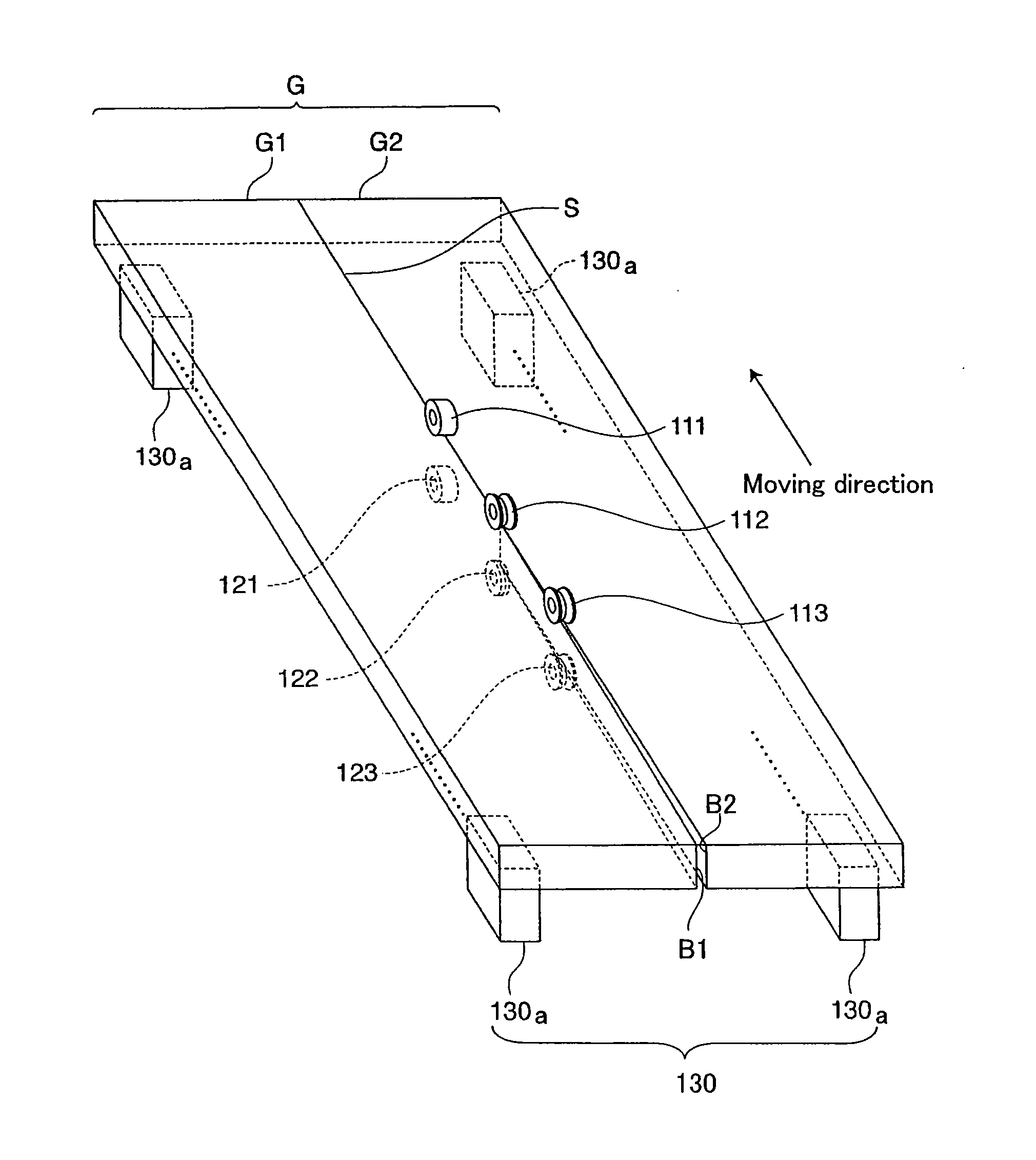
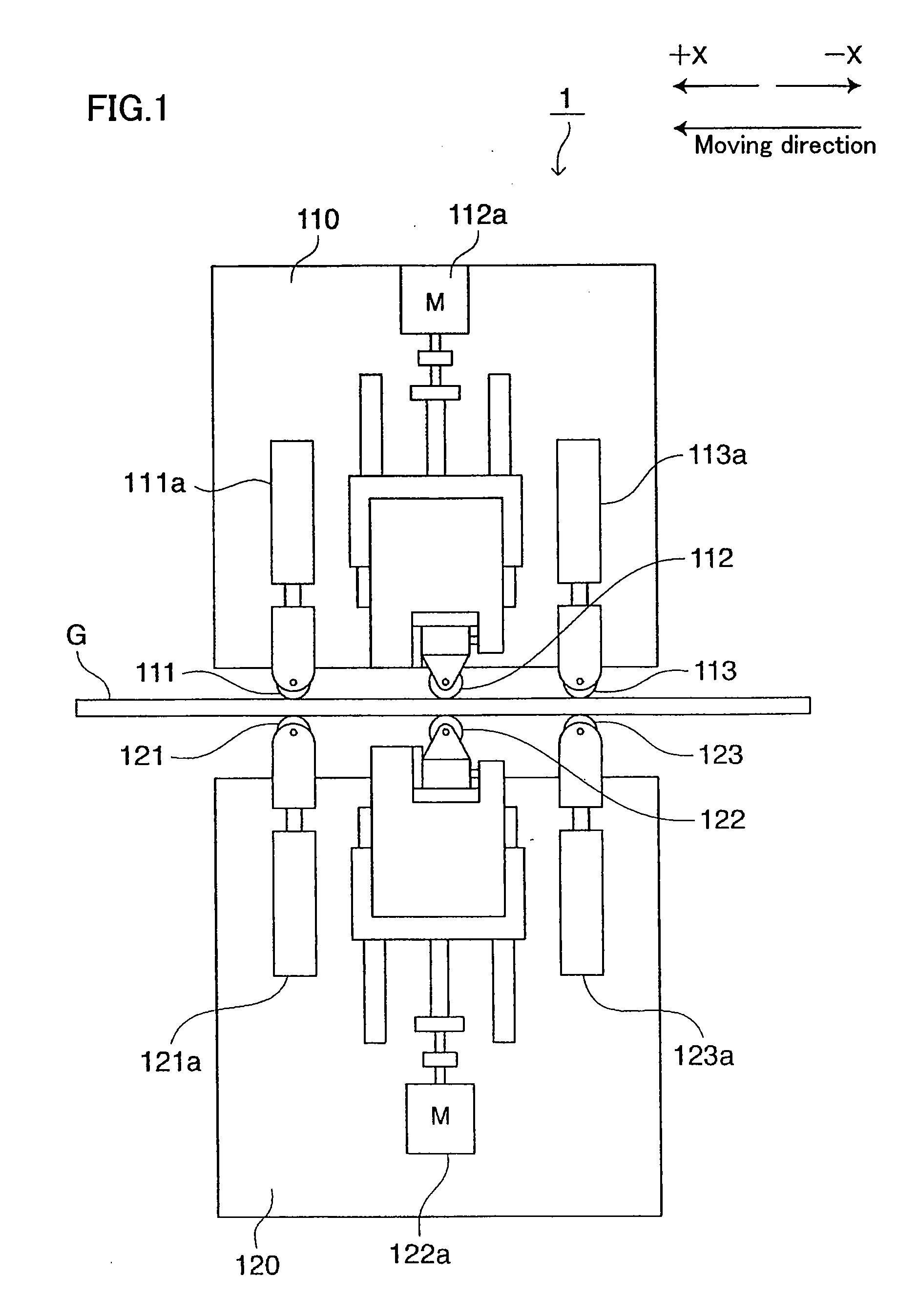
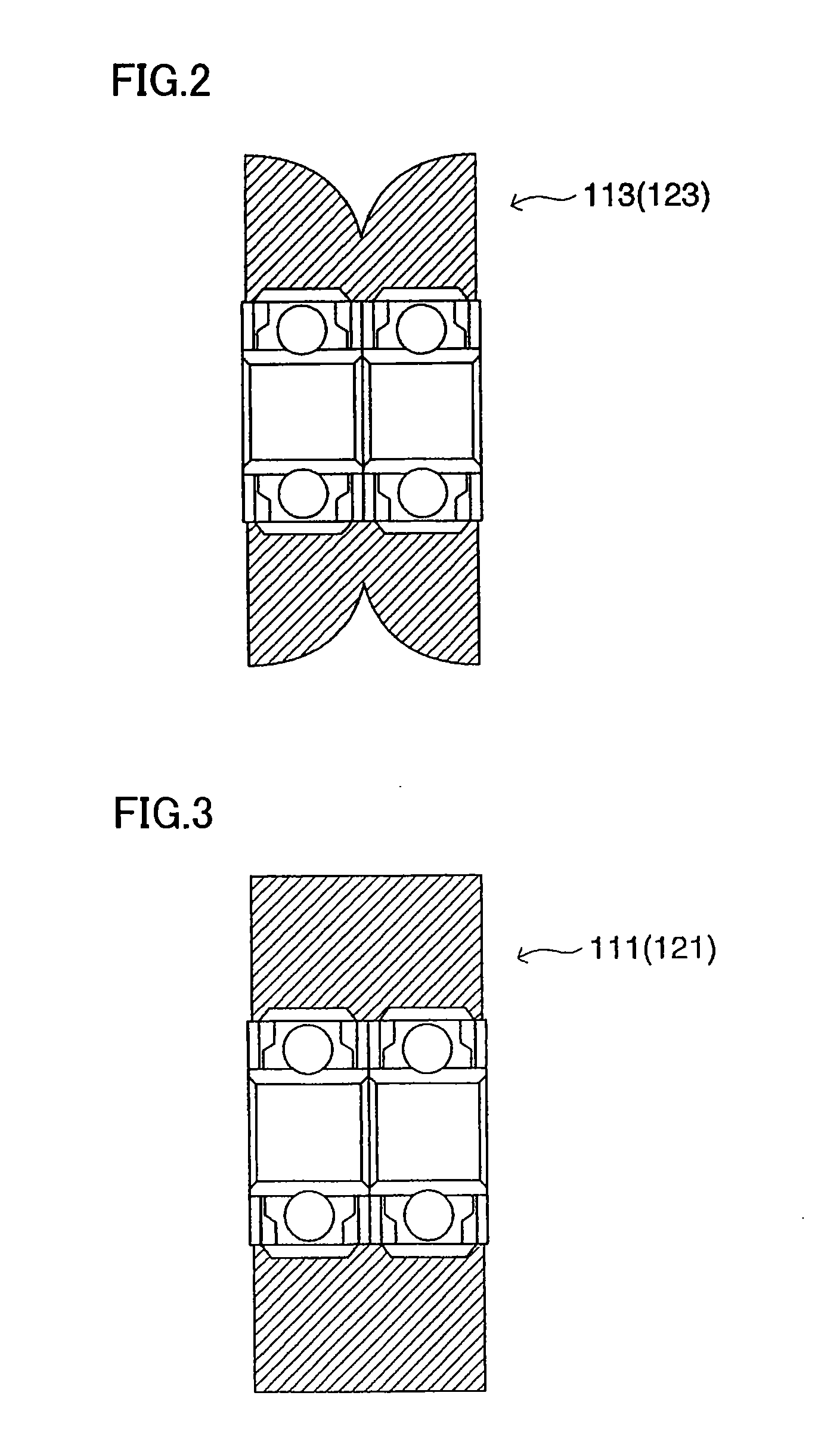
[0053]A cutting apparatus 1 according to Embodiment 1 of the present invention will be described with reference to FIG. 1. The cutting apparatus 1 shown in FIG. 1 is for performing a break step of cutting a substrate G with a scribe line formed thereon. The cutting apparatus 1 includes an upper roller holding section 110 and a lower roller holding section 120 arranged below the upper roller holding section 110. The substrate G is, for example, a brittle material substrate such as glass substrate, and the substrate G is mounted on a table 130 (see FIG. 5). The table 130 shown in FIG. 5 includes a plurality of table structuring members 130a, and the table 130 is a vacuum suctioning table functioning as a substrate holding section, wherein each of the plurality of table structuring members 130a is, for example, provided with a mechanism for holding the substrate G by vacuum-suction. The table 130 holds only side portions of the substrate G such that the lower roller holding portion 120...

embodiment 2

[0095]The cut-face separating section included in the cutting apparatus according to Embodiment 1 of the present invention described above moves the substrate portions cut in the break step in directions to separate the substrate portions from each other while cut-face separating section included in a cutting apparatus according to Embodiment 2 is characterized by moving one of cut substrate portions in an upper and lower direction, in addition to the feature of Embodiment 1.

[0096]A cutting apparatus 2 according to Embodiment 2 shown in FIG. 10 uses separating first rollers 113D (cross-sectional view thereof shown in FIG. 7) in place of the first separating roller 113 and the second separating roller 123 in the cutting apparatus 1 according to Embodiment 1 shown in FIG. 1. The first separating roller 113D arranged above the substrate G and the second separating roller 113D arranged below the substrate G are arranged on the same side (which corresponds to the substrate portion G1 whi...

embodiment 3

[0103]The cut-face separating sections included in the cutting apparatuses according to Embodiments 1 and 2 of the present invention described above have structures that the rollers or belts contacting the substrate are deformed, or the rotation axis is inclined with respect to the moving direction, so that the substrate portions cut in the break step are separated from each other. Instead thereof, a cut-face separating section included in a cutting apparatus according to Embodiment 3 is characterized by moving cut substrate portions by controlling the position of one of the cut substrate portions using a roller for pressing a surface of the substrate G and a roller having an inclined outer circumferential surface with the outer-diameter thereof gradually decreased along its axial direction to hold one of the cut substrate portions therebetween.

[0104]In a cutting apparatus 3 according to Embodiment 3 shown in FIG. 11, the first separating roller 113 and the second separating roller ...


PUM

PropertyMeasurementUnit
brittleaaaaaaaaaa
pressureaaaaaaaaaa
forceaaaaaaaaaa

Abstract

A brittle material substrate cutting method and cutting apparatus are provided, which prevent cut faces of a brittle material substrate from contacting each other after the cutting in a break step of continuously cutting the brittle material substrate, so that a damage or contamination on the brittle material substrate due to the contact can be prevented. A brittle material substrate cutting apparatus includes: a cutting section (112, 122) for applying a pressing force in a vicinity of a scribe line S formed on a substrate G and cutting the pressed portion of the substrate G; and a holding section moving parallel to the scribe line S while holding the cutting section. The brittle material substrate cutting apparatus continuously cuts the substrate G along the scribe line S. The brittle material substrate cutting apparatus further includes: a cut-face separating section (113, 123), provided in the holding section, for holding and pressing at least one part of cut substrate portions of the substrate G, wherein the cut substrate portions are generated as a result of the cutting and they oppose each other, and moving cut faces of the cut substrate portions approximately parallel to a main face of the substrate G and in directions to separate the cut faces from each other.

Description

CROSS-REFERENCE TO RELATED APPLICATIONS[0001]This application is U.S. national phase filing under 35 U.S.C. §371 of PCT / JP2006 / 310541 filed May 26, 2006 and claims priority from Japanese Application No. 2005-187324 which was filed on May 30, 2005.TECHNICAL FIELD[0002]The present invention relates to a cutting apparatus and a cutting method for a brittle material substrate (e.g., glass, semiconductor and ceramic), and in particular, the present invention relates to a brittle material substrate cutting apparatus and a brittle material substrate cutting method for cutting a brittle material substrate by applying a force along a scribe line formed on the brittle material substrate.BACKGROUND ART[0003]A brittle material substrate is generally cut using a method to be described below. First, a scribe line including a vertically-formed crack (hereinafter, referred to as “vertical crack”) is formed along a desired line to be cut on one surface of a brittle material substrate using such as s...

Claims


Application Information

Patent Timeline
Patent Type & Authority Applications(United States)
IPC IPC(8): B26F3/00B26D3/08B31B1/25B31B50/25
CPCB28D5/0029B28D5/0011C03B33/033B65G2249/04B28D5/0023B28D1/222Y10T83/0333Y10T225/30Y10T225/325Y02P40/57B28D5/00
Inventor NISHISAKA, YUKIOTODA, KENJIINOUE, SHUICHIKUMAGAI, TORU
Owner MITSUBOSHI DIAMOND IND CO LTD
Why Eureka
Try Eureka