Pressure bulkhead for an aerospace fuselage

a technology for aerospace fuselages and bulkheads, which is applied in the direction of fuselage bulkheads, fuselages, transportation and packaging, etc., can solve the problems of difficult manufacturing processes for both metal and composite materials, weight increment of structures, and use of expensive materials and/or processes

Active Publication Date: 2010-03-18
AIRBUS OPERATIONS GMBH
View PDF8 Cites 13 Cited by
  • Summary
  • Abstract
  • Description
  • Claims
  • Application Information

AI Technical Summary

Benefits of technology

[0010]In view of the above it is one of the objects of the present invention to provide a pressure bulkhead for an aerospace fuselage which avoids or mitigates the disadvantages mentioned above.

Problems solved by technology

The main disadvantages of the existing solutions of a pressure bulkhead are the following: the weight increment of the structure necessary for the prevention of static instabilities; the difficult manufacturing processes for both the metal and the composite materials solutions; the use of expensive materials and / or processes; and the difficult maintenance of the structures next to the pressure bulkhead.
With regard to the weight increment the main structural problem is the static instability caused by shear and compression forces.
These instabilities arise in correspondence of load states as the lateral maneuvers with high twisting moments (high shear stresses), and in correspondence of negative pressure gradients (high compression stresses), such as an eventual rapid loss of altitude of the aircraft.
Regarding the difficult manufacturing due to the presence of the stiffeners and due to the double curvature of the above mentioned bulkheads, the manufacturing process results in a very complex and expensive task.
Such materials are as well expensive as their manufacturing processes, especially in the case of composite sandwich stiffeners.
With regard to the difficult maintenance, due to the curvature adopted and the related space occupation, it results in a difficult access to the structure in the back of the pressure bulkhead and a difficult cleaning of the areas close to the attachment of the bulkhead to the correspondent frame.

Method used


Image

  • Pressure bulkhead for an aerospace fuselage
  • Pressure bulkhead for an aerospace fuselage
  • Pressure bulkhead for an aerospace fuselage

Examples


first embodiment

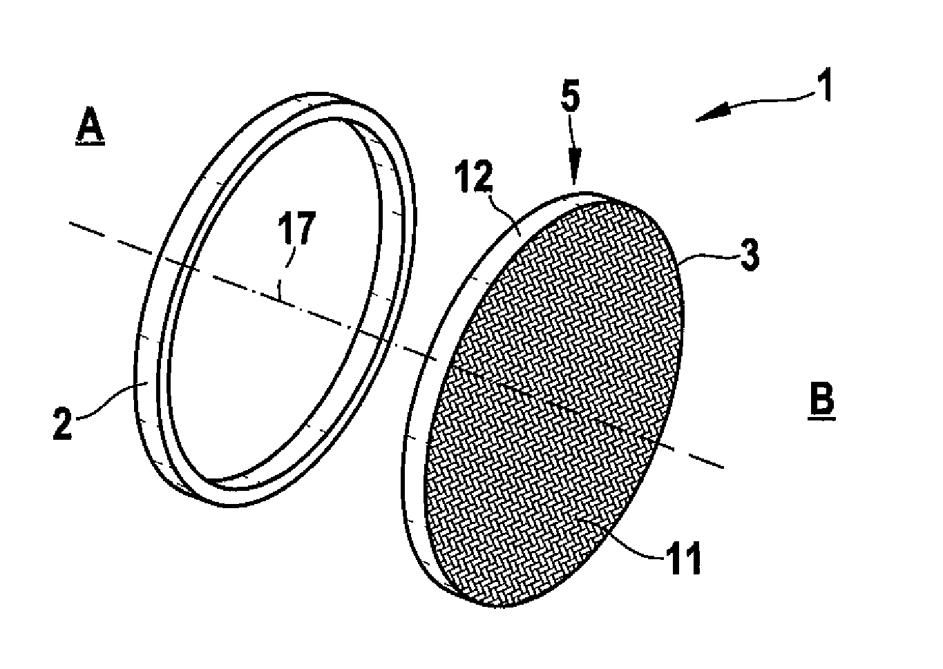
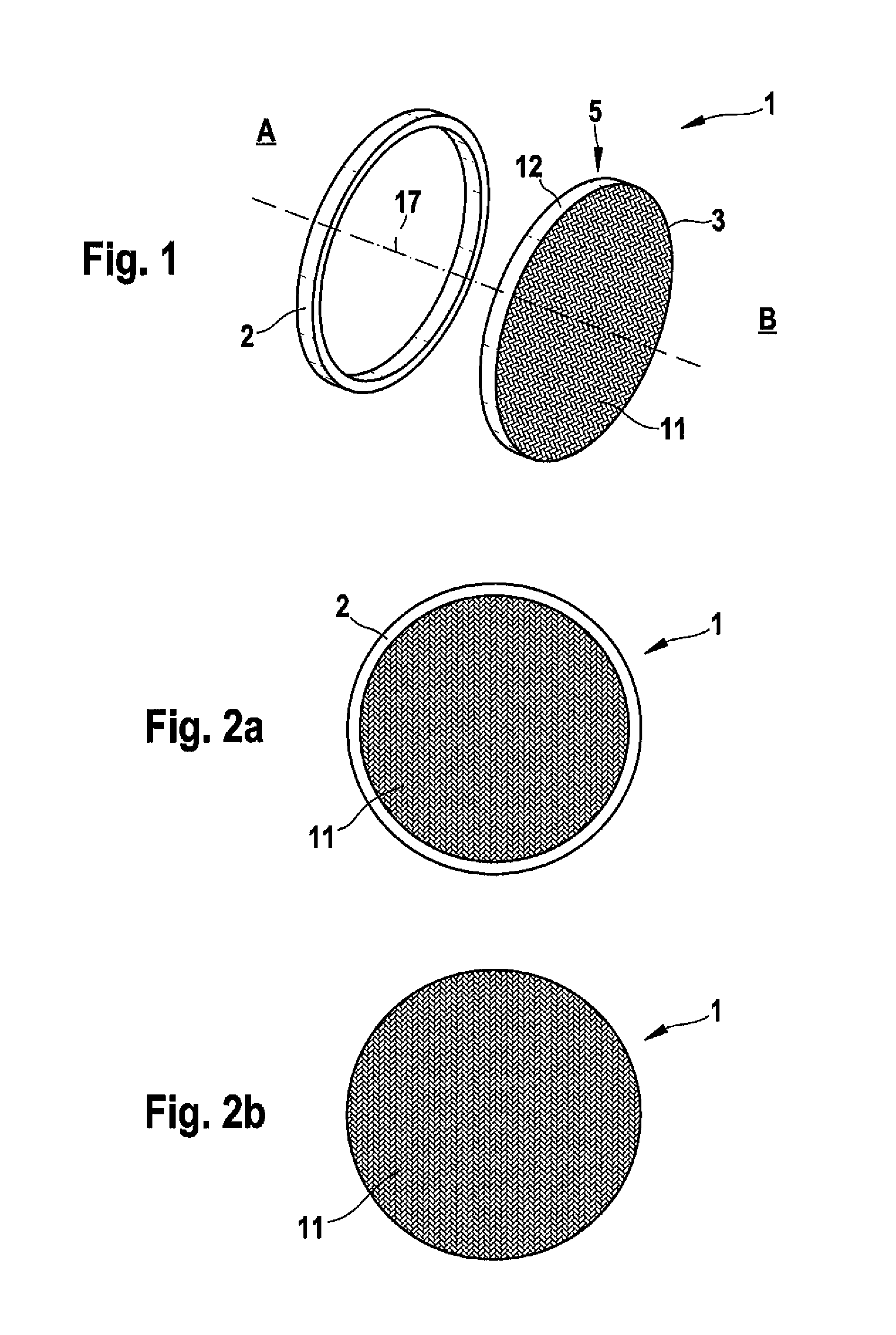
[0030]FIG. 1 is a perspective exploded view of the present invention. It shows a pressure bulkhead 1 having a longitudinal axis 17. In this embodiment the bulkhead 1 has a circular or oval shape and comprises a frame 2 and a bulkhead main portion 3. The bulkhead main portion 3 consists of a reticular component 5, which is formed by a braided cloth 11 with a peripheral rim 12.

[0031]On the left side of the frame 2 there is an inside of a not shown interior of an aircraft, indicated by the reference sign A. Reference sign B indicates an outside, e.g. the rear of the tail of the aircraft not shown.

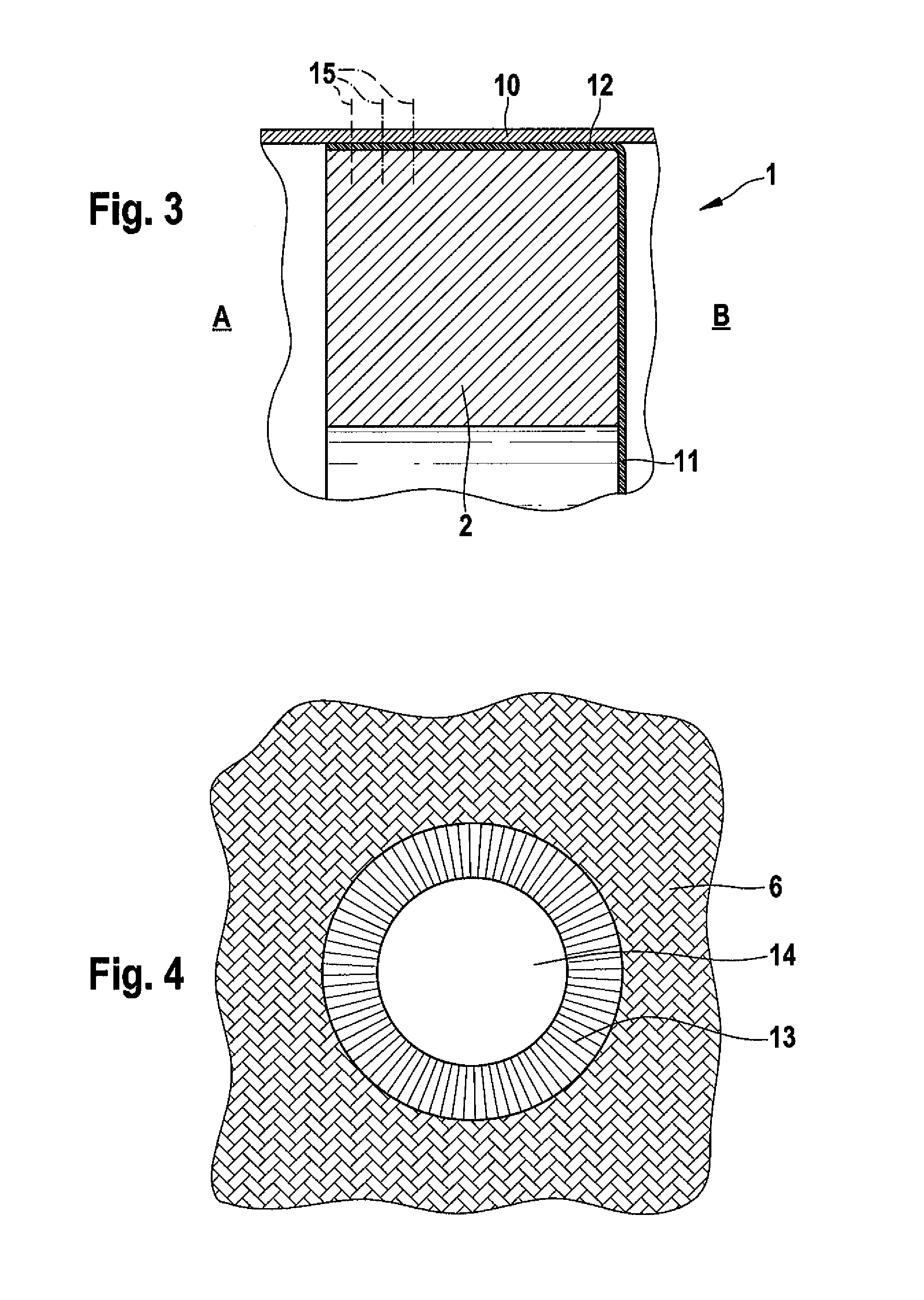
[0032]The frame 2 supports the bulkhead main portion 3 which is fixed to the frame 2 as shown in FIG. 2 and in an enlarged sectional view in FIG. 3. FIG. 2 (above) illustrates a plan view of the assembled bulkhead 1 from the inside A and from the outside B (below). As can be seen from FIG. 2, the cloth 11 is attached to the frame 2 from the outside B as illustrated in FIG. 3.

[0033]FIG. 3 is an...

second embodiment

[0040]FIG. 6 is a perspective exploded view of the present invention.

[0041]It illustrates a pressure bulkhead 1′ having a longitudinal axis 17. In this example, the bulkhead 1 has a circular or oval shape and comprises a frame 2 and a bulkhead main portion 3. The bulkhead main portion 3 consists of two reticular components 5′ and 5″, which are formed by ligament elements 6′, 6″ in the shape of belts.

[0042]On the left side of the frame 2 there is the inside, indicated by the reference sign A of a not shown interior of an aircraft. Reference sign B indicates the outside, e.g. the rear part of the tail of the aircraft not shown.

[0043]The frame 2 supports the bulkhead main portion 3 which is fixed to the frame 2 as shown in FIG. 9 similar as shown in FIG. 3.

[0044]The ligaments 6′ of the reticular component 5′ are arranged in a manner so that they extend radially in at least one first layer and one second layer, respectively and form at least two retaining layers for a sealing element 4 ...


PUM


Abstract

A pressure bulkhead for an aerospace fuselage includes a bulkhead main portion having an approximately flat shape in unloaded state; and a frame supporting and connecting said bulkhead main portion to the fuselage; wherein said bulkhead main portion includes an airtight structure having a reticular component.

Description

FIELD OF THE INVENTION[0001]The present invention relates to a pressure bulkhead for an aerospace fuselage.BACKGROUND OF THE INVENTION[0002]A pressure bulkhead belongs to the internal structures of an aircraft fuselage and is used for ensuring a pressure tight interior, e.g. in the tail section of said aircraft. The bulkhead consists generally of rigid shells, e.g. with a single or double curvature, made of metal or composite materials, often reinforced by so called stiffeners.[0003]The main disadvantages of the existing solutions of a pressure bulkhead are the following: the weight increment of the structure necessary for the prevention of static instabilities; the difficult manufacturing processes for both the metal and the composite materials solutions; the use of expensive materials and / or processes; and the difficult maintenance of the structures next to the pressure bulkhead.[0004]With regard to the weight increment the main structural problem is the static instability caused ...

Claims


Application Information

Patent Timeline
Patent Type & Authority Applications(United States)
IPC IPC(8): B64C1/10
CPCB64C1/10
Inventor BASSO, PASQUALE
Owner AIRBUS OPERATIONS GMBH
Why Eureka
Try Eureka