Rotor for Motor

a rotor and motor technology, applied in the direction of dynamo-electric machines, magnetic circuit rotating parts, magnetic circuit shapes/forms/construction, etc., can solve the problems of disengagement of magnets, affecting the operation of motors, etc., to achieve the effect of simple structur

Inactive Publication Date: 2010-03-18
SUNONWEALTH ELECTRIC MACHINE IND
View PDF3 Cites 21 Cited by
  • Summary
  • Abstract
  • Description
  • Claims
  • Application Information

AI Technical Summary

Benefits of technology

[0008]The primary objective of the present invention is to provide a rotor for a motor that includes a shaft and a plastic magnet securely engaged on the shaft wile having a simple structure.

Problems solved by technology

However, the magnet 72 is liable to break.
However, the adhesive is liable to lose its adhesion due to deterioration, resulting in disengagement of the magnet 72 from the shaft 71 or undesired rotation of the magnet 72 relative to the shaft 71.
However, the rotor 8 has a complicated structure and, thus, fails to provide assembling convenience.
Conclusively, the rotors 8 and 9 are still too complicated and, thus, not easy to assemble, while the rotor 7 is simple but has insecure engagement between the magnet 72 and the shaft 71.

Method used


Image

  • Rotor for Motor
  • Rotor for Motor
  • Rotor for Motor

Examples


first embodiment

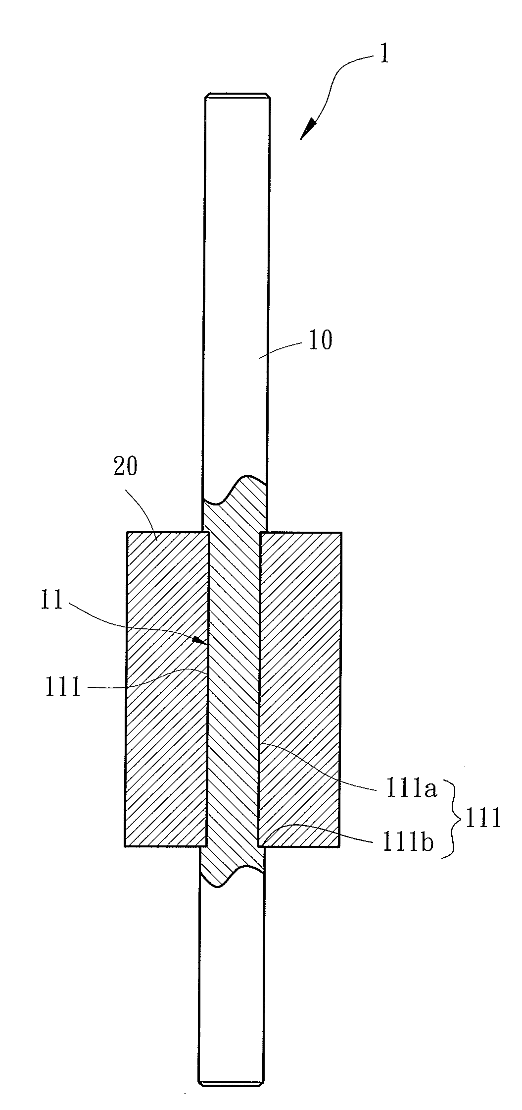
[0028]FIGS. 4, 5 and 6 show a rotor 1 for a motor of a first embodiment according to the preferred teachings of the present invention. According to the preferred form shown, the rotor 1 includes a shaft 10 and a plastic magnet 20. The shaft 10 includes a positioning portion 11 on an outer periphery thereof. The positioning portion 11 includes a plurality of grooves 111 each extending in a direction parallel to and spaced from the longitudinal axis of the shaft 10. Furthermore, the grooves 111 are spaced from one another in a circumferential direction. By providing the longitudinally extending grooves 111, the positioning portion 11 has non-circular cross sections perpendicular to the longitudinal axis of the shaft 10. The plastic magnet 20 is formed on the outer periphery of the shaft 10 by injection molding, with the inner periphery of the plastic magnet 20 engaged with the groves 111 of the positioning portion 11. Thus, the plastic magnet 20 is prevented from rotating relative to ...

second embodiment

[0029]FIGS. 7 and 8 show a rotor 2 for a motor of a second embodiment according to the preferred teachings of the present invention. According to the preferred form shown, the rotor 2 includes a shaft 10a and a plastic magnet 20. The shaft 10a includes a positioning portion 12 on an outer periphery thereof. The positioning portion 12 includes a rugged surface 121 on the outer periphery of the shaft 10a. By providing the rugged surface 121, the positioning portion 12 has non-circular cross sections perpendicular to the longitudinal axis of the shaft 10a. The plastic magnet 20 is formed on the outer periphery of the shaft 10a by injection molding, with the inner periphery of the plastic magnet 20 engaged with the rugged surface 121 of the positioning portion 12. Thus, the plastic magnet 20 is prevented from rotating relative to the shaft 10a and from disengaging from the shaft 10a.

third embodiment

[0030]FIGS. 9 and 10 show a rotor 3 for a motor of a third embodiment according to the preferred teachings of the present invention. According to the preferred form shown, the rotor 3 includes a shaft 10b and a plastic magnet 20. The shaft 10b includes a positioning portion 13 on an outer periphery thereof. The positioning portion 13 includes two recesses 131 each including a flat bottom face having a spacing to the longitudinal axis smaller than the outer periphery of the shaft 10b. By providing the recesses 131, the positioning portion 13 has non-circular cross sections perpendicular to the longitudinal axis of the shaft 10b. The plastic magnet 20 is formed on the outer periphery of the shaft 10b by injection molding, with the inner periphery of the plastic magnet 20 engaged with the recesses 131 of the positioning portion 13. Thus, the plastic magnet 20 is prevented from rotating relative to the shaft 10b and from disengaging from the shaft 10b. It can be appreciated that the pos...


PUM


Abstract

A rotor for a motor includes a shaft having an outer periphery with a positioning portion. The positioning portion has non-circular cross sections perpendicular to a longitudinal axis of the shaft. A plastic magnet is formed on the outer periphery of the shaft by injection molding. The plastic magnet includes an inner periphery engaged with the positioning portion. Thus, the plastic magnet is prevented from disengaging from the shaft and from rotating relative to the shaft. As a result, the rotor has enhanced engaging effect between the shaft and the plastic magnet. Furthermore, the rotor has a simple structure to allow easy assembly.

Description

BACKGROUND OF THE INVENTION[0001]1. Field of the Invention[0002]The present invention relates to a rotor for a motor and, more particularly, to a rotor for an inner rotor type motor.[0003]2. Description of the Related Art[0004]Motors currently available from the market include outer-rotor type and inner-rotor type. Since motors of inner-rotor type are more stable than outer-rotor type during rotation, the inner-rotor type motors can fulfill the heat dissipating needs in electronic products having developing trends in high speed, functional integrity, and miniaturization.[0005]FIG. 1 shows a conventional rotor 7 for an inner rotor type motor. The rotor 7 includes a shaft 71 and a magnet 72. The magnet 72 includes an axial hole 721 through which the shaft 71 is extended and engaged. In an approach, the shaft 71 is engaged with the magnet 72 by tight coupling. However, the magnet 72 is liable to break. In another approach, the shaft 71 is engaged with the inner periphery of the axial h...

Claims


Application Information

Patent Timeline
Patent Type & Authority Applications(United States)
IPC IPC(8): H02K21/14
CPCH02K1/02H02K1/28H02K1/2733
Inventor HORNG, ALEXYIN, TSO-KUO
Owner SUNONWEALTH ELECTRIC MACHINE IND
Why Eureka
Try Eureka