Liquid crystal display unit

a technology of liquid crystal display unit and liquid crystal, which is applied in the direction of optics, optical light guides, instruments, etc., to achieve the effects of effective cooling of led light sources, good optical properties, and efficient light making

Active Publication Date: 2010-03-18
MAXELL HLDG LTD
View PDF17 Cites 88 Cited by
  • Summary
  • Abstract
  • Description
  • Claims
  • Application Information

AI Technical Summary

Benefits of technology

[0030]According to the present invention, a protrusion portion, provided on a chassis member, extending to at least parts of an optical guiding board and a reflection sheet and a reflective thermal insulation member, provided on the protrusion portion, extending from an end portion of the LED light source block to at least parts of the optical guiding board and the reflection

Problems solved by technology

Thirdly, a combination of light-emitting devices of red, green and blue as the LED light source provides high color duplicability.
However, use of structures disclose

Method used


Image

  • Liquid crystal display unit
  • Liquid crystal display unit
  • Liquid crystal display unit

Examples


first embodiment

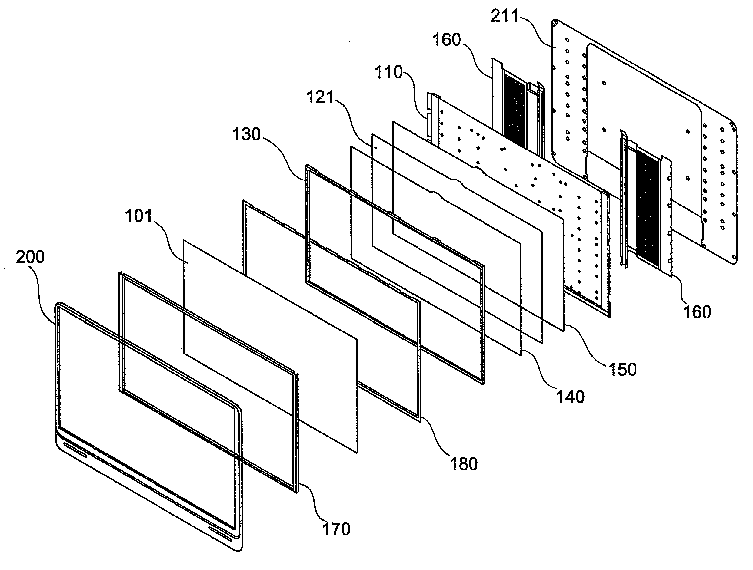
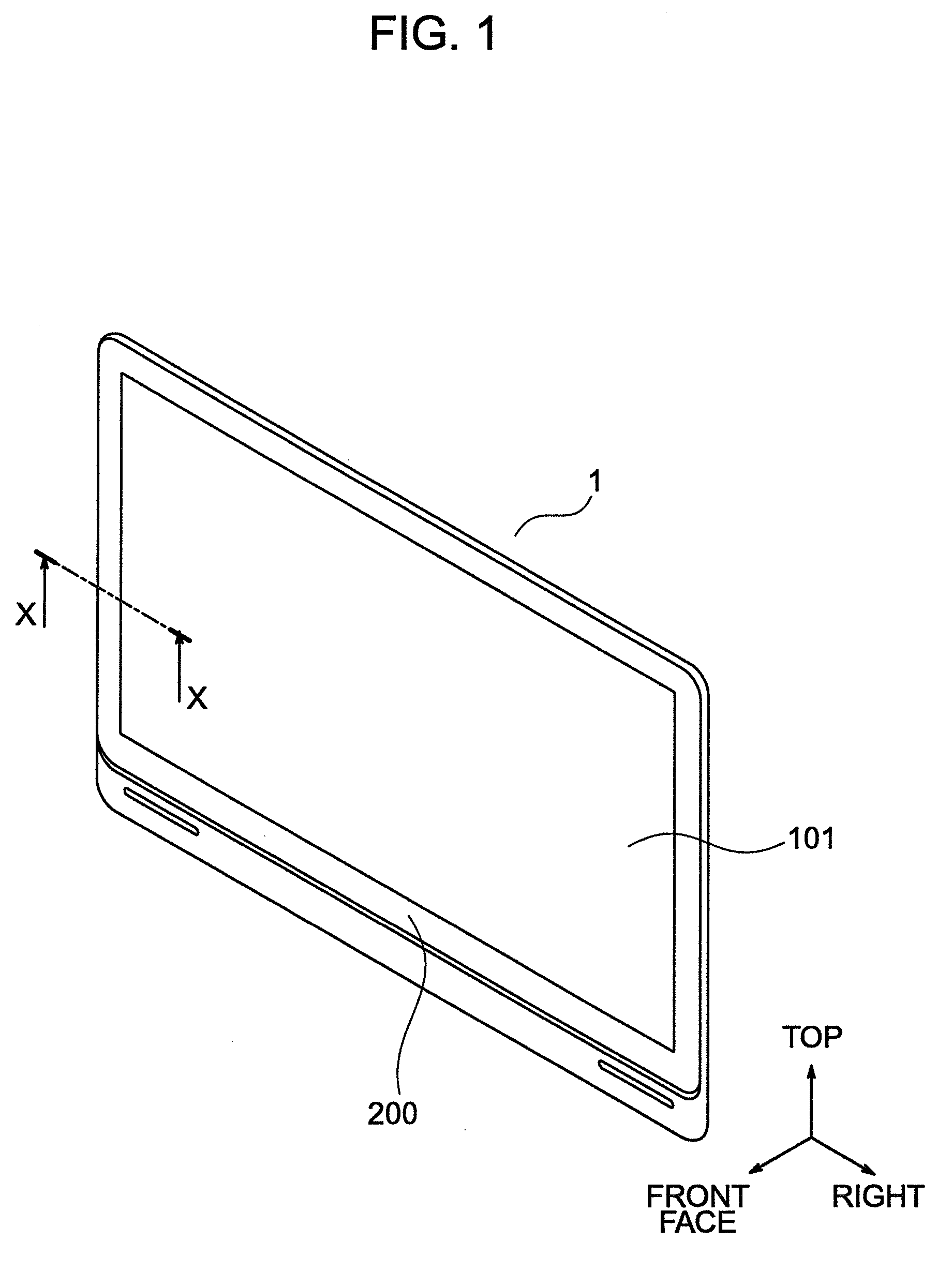
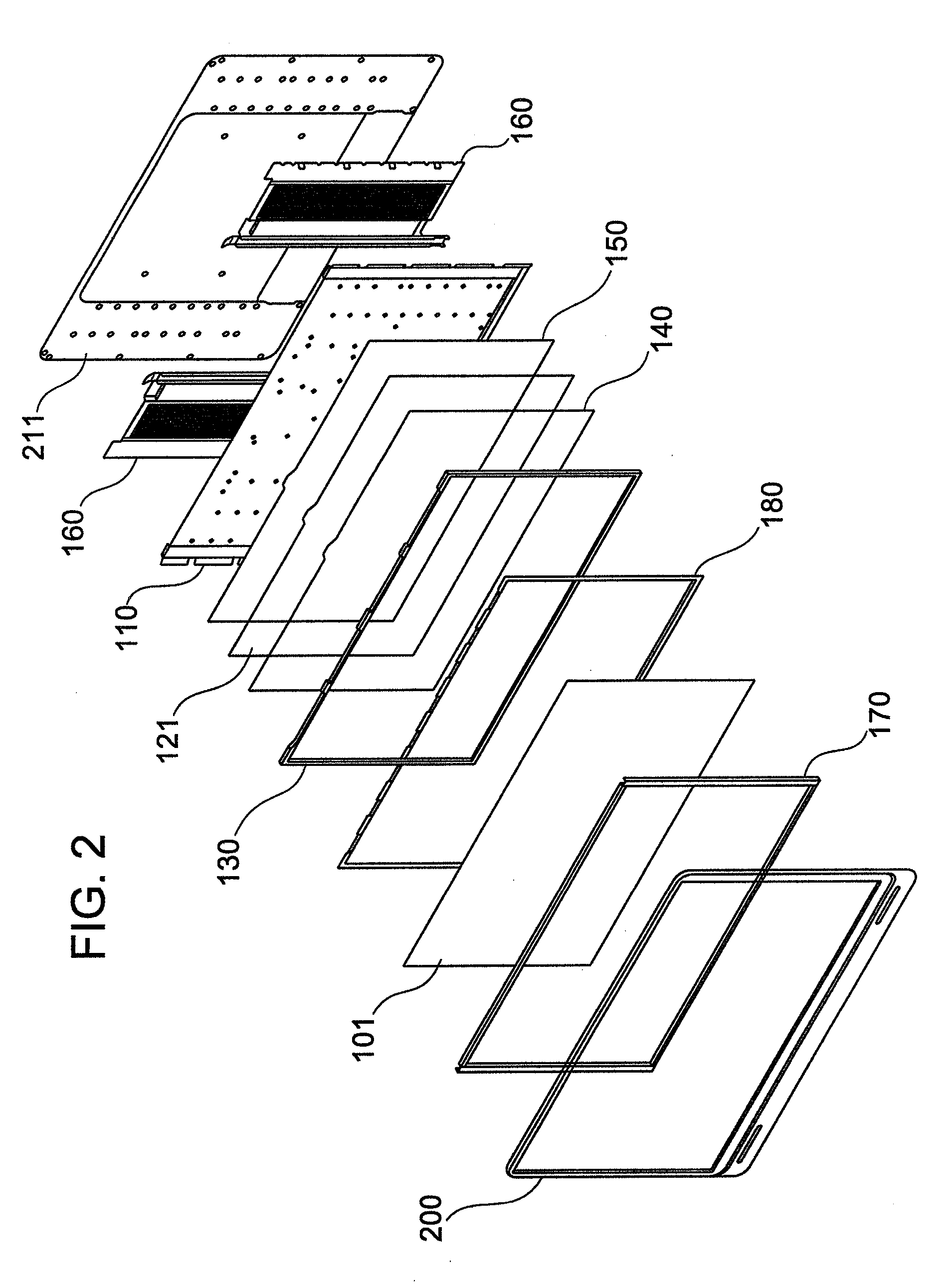
[0047]FIG. 1 is a perspective view of a liquid crystal display unit according to an embodiment of the present invention. A liquid crystal display unit 1 includes a liquid crystal panel 101 and an appearance frame 200 which is a housing surrounding a circumference thereof. For the purpose of description, a top and a bottom and a front face and a rear face thereof are defined with respect to a display screen of the liquid crystal panel 101. Specifically, when a user who views the liquid crystal display unit 1 opposes the display screen of the liquid crystal panel 101, the display screen side which is a front side is defined as “front face”, the deep side is defined as “rear face” and the right side and the left side of the liquid crystal panel in a horizontal direction toward the user are defined as “right” and “left” respectively. In addition, the top side and the bottom side of the liquid crystal panel in a perpendicular direction toward the user are defined as “top” and “bottom” re...

second embodiment

[0085]Referring next to FIGS. 9 to 13, a liquid crystal display unit according to a second embodiment of the present invention will be described below. One of the features of the present embodiment is that a reflective thermal insulation member formed with a reflecting surface on a surface on an optical guiding board side is used as a heat insulating member.

[0086]FIG. 9 is a schematic configurational view when the liquid crystal display unit according to the present embodiment is seen from a display face side. FIG. 10 is a sectional view taken along line A-A′ in FIG. 1.

[0087]In the present embodiment, a vertical direction in FIG. 9 is defined as a vertical direction and a horizontal direction in FIG. 9 as a horizontal direction. In addition, a liquid crystal panel 3 side in FIG. 10 is defined as a front face side and a rear face cover 4 side in FIG. 10 as a rear face side.

[0088]As illustrated in FIG. 9, when a liquid crystal display unit 1 is seen from a display face side, a liquid ...

third embodiment

[0122]Next, a liquid crystal display unit according to a third embodiment of the present invention will be described below.

[0123]FIG. 13 is a schematic sectional view of an end portion of a liquid crystal display unit according to a third embodiment and corresponds to FIG. 12 in a second embodiment illustrated in FIGS. 9 to 12. Just as in FIG. 12, for easy understanding of figures, any of an appearance frame, rear face cover and electric circuit board is not illustrated.

[0124]The present embodiment is the same as the second embodiment illustrated in FIGS. 9 to 12 except a metal frame 9 and a reflective thermal insulation member 20. The reflective thermal insulation member 20 has a reflection sheet 20b on the front face side and is constructed from a laminated body of a member 20a a part of which is hollow on the rear face side. Preferably, the member 20a is made of resin, particularly for high heat resistance. Such a member 20a can be easily manufactured by, for example, a resin mol...


PUM


Abstract

There is provided a slim liquid crystal display unit having a large screen by providing a slim structure capable of sufficiently radiating the heat from a light source. The liquid crystal display unit according to the present invention includes: a liquid crystal panel; an optical guiding board installed on a rear face thereof; a pair of light source-mounted substrate disposed, opposing right and left side faces thereof; a light source mounted on the light source-mounted substrate; a metal frame connected on the opposite side to the optical guiding board of the light source-mounted substrate; a chassis member for supporting the optical guiding board and a reflection sheet group; and a thermal diffusion member fixed onto the metal frame along with the chassis member. The chassis member has a stepped portion in the vicinity of the light source. Between the stepped portion and the reflection sheet group, a thermal insulation member is attached.

Description

BACKGROUND OF THE INVENTION [0001](1) Field of the Invention[0002]The present invention relates to a liquid crystal display unit having an edge light (side light) type backlight. In particular, the present invention relates to a liquid crystal display unit having good optical properties by improving light extraction efficiency and inhibiting deterioration of an optical member.[0003](2) Description of the Related Art[0004]The liquid crystal display unit displays an image by controlling the optical transparency of a large number of pixels formed behind a liquid crystal panel face. The liquid crystal panel has no own light emission function and a liquid crystal display unit, generally referred to as “transmission type”, is provided with a light source called a “backlight” and the light emitted from the backlight is spread onto a rear face side of a liquid crystal panel.[0005]The following two types of backlight are available: one type in which a large number of light sources are distri...

Claims


Application Information

Patent Timeline
IPC IPC(8): G02F1/13357G02F1/1333
CPCG02B6/0031G02B6/0085G02B6/0073
Inventor YAMASHITA, YOSHIHARUMORISHIMA, AKITOSHISATO, KATSUNARINISHIJIMA, NORIYOOHASHI, SHIGEOMIITSU, TAKESHIOGURA, HIROYOSHIHOSONO, HIROKISATO, KOICHI
Owner MAXELL HLDG LTD
Why Eureka
Try Eureka