
Telephony services in mobile IP networks

a mobile ip network and telephony service technology, applied in the field of mobile ip network telephony services, can solve the problems that the method cannot always be performed in the 3sup>rd /sup>generation mobile ip network based on the ipt subscribers, and is difficult to be easily used by ipt subscribers. , to achieve the effect of convenient setup

Inactive Publication Date: 2010-03-18
GOOGLE TECH HLDG LLC
View PDF21 Cites 71 Cited by
  • Summary
  • Abstract
  • Description
  • Claims
  • Application Information

AI Technical Summary

Benefits of technology

The present invention provides a system and method for providing location-based services and emergency calls in a 3G mobile network. One application is that a visiting subscriber can make an emergency call using their mobile phone, which is connected to a local network without needing to authenticate or bill. The system selects a Public Safety Answering Point (PSAP) to route the call to based on the service area, and forwards the call to the selected PSAP without billing. The approximate geographic location of the subscriber is transferred to the PSAP or CSCF at the same time as the call is connected. This allows for easy and unrestricted use of emergency calls without needing a SIM card or charging. The access network can also control the PDP contexts used for emergency calls to prevent misuse or fraud.

Problems solved by technology

However, when providing voice call services, such Mobile IP Telephony (MIPT) networks have several problems which are not present in conventional 2nd generation cellular networks.
For example, while cellular subscribers can often roam between 2nd generation cellular networks, it is difficult for IP Telephony (IPT) subscribers of MIPT networks to easily access the same services available in their home network when they are visiting in other networks.
However, this method cannot always be performed in 3rd generation mobile IP networks based on the UMTS standard, since the Cell ID or location information may not always be available to a call control entity due to the way the emergency calls are setup.

Method used


Image

  • Telephony services in mobile IP networks
  • Telephony services in mobile IP networks
  • Telephony services in mobile IP networks

Examples


Embodiment Construction

[0022]The foregoing and a better understanding of the present invention will become apparent from the following detailed description of example embodiments and the claims when read in connection with the accompanying drawings, all forming a part of the disclosure of the invention. While the foregoing and following written and illustrated disclosure focuses on disclosing example embodiments of the invention, it should be clearly understood that the same is by way of illustration and example only and is not to be taken by way of limitation, the spirit and scope of the present invention being set forth by the claims in the patent issuing from this application.

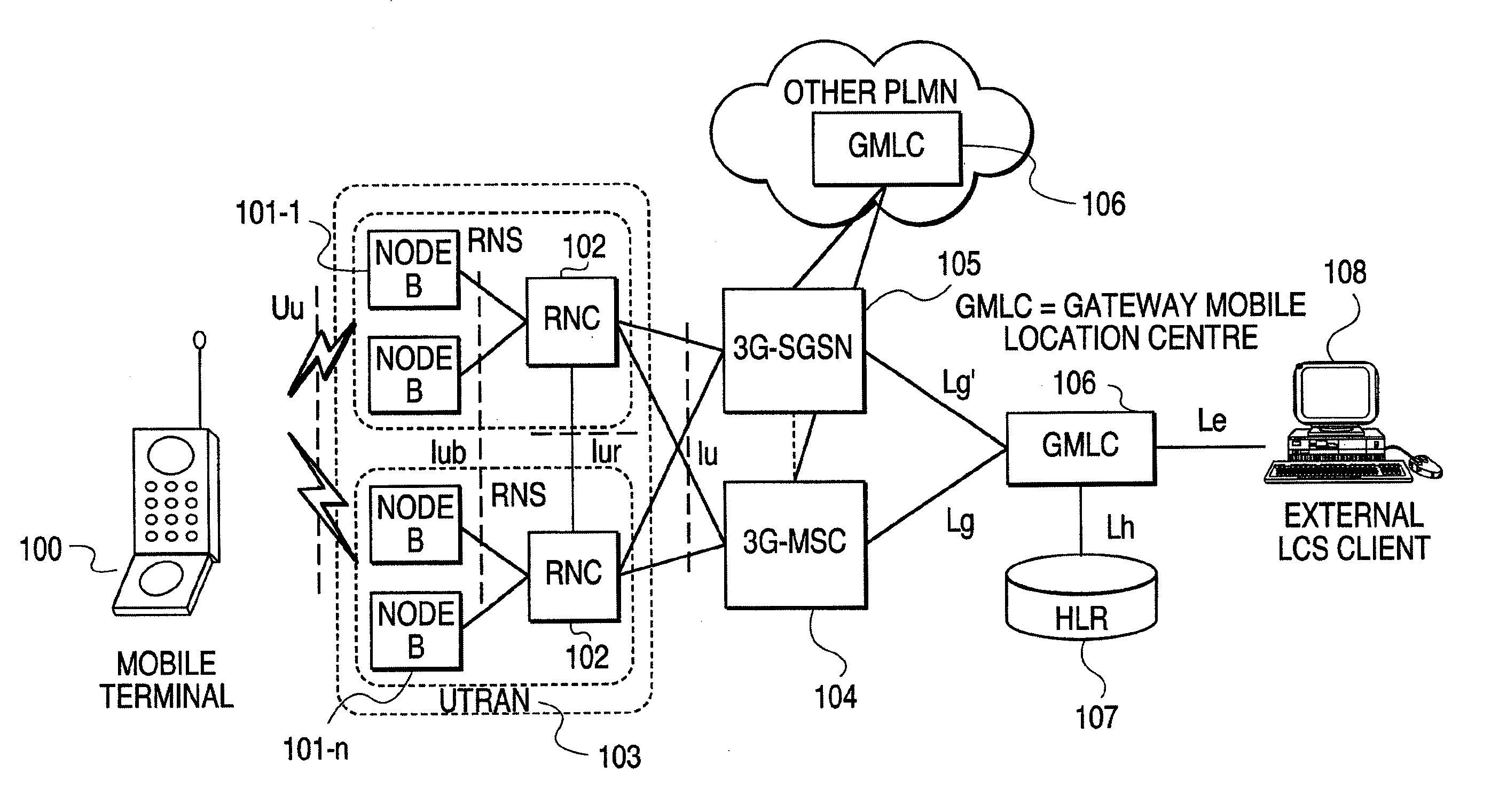
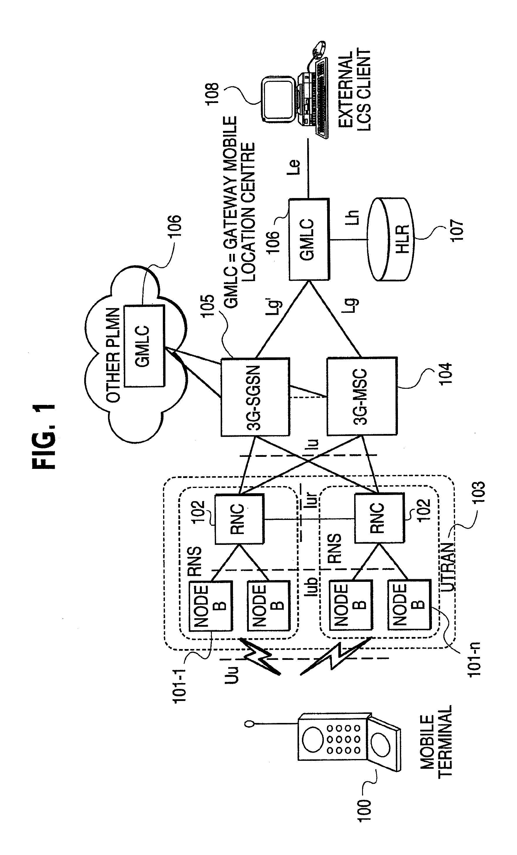
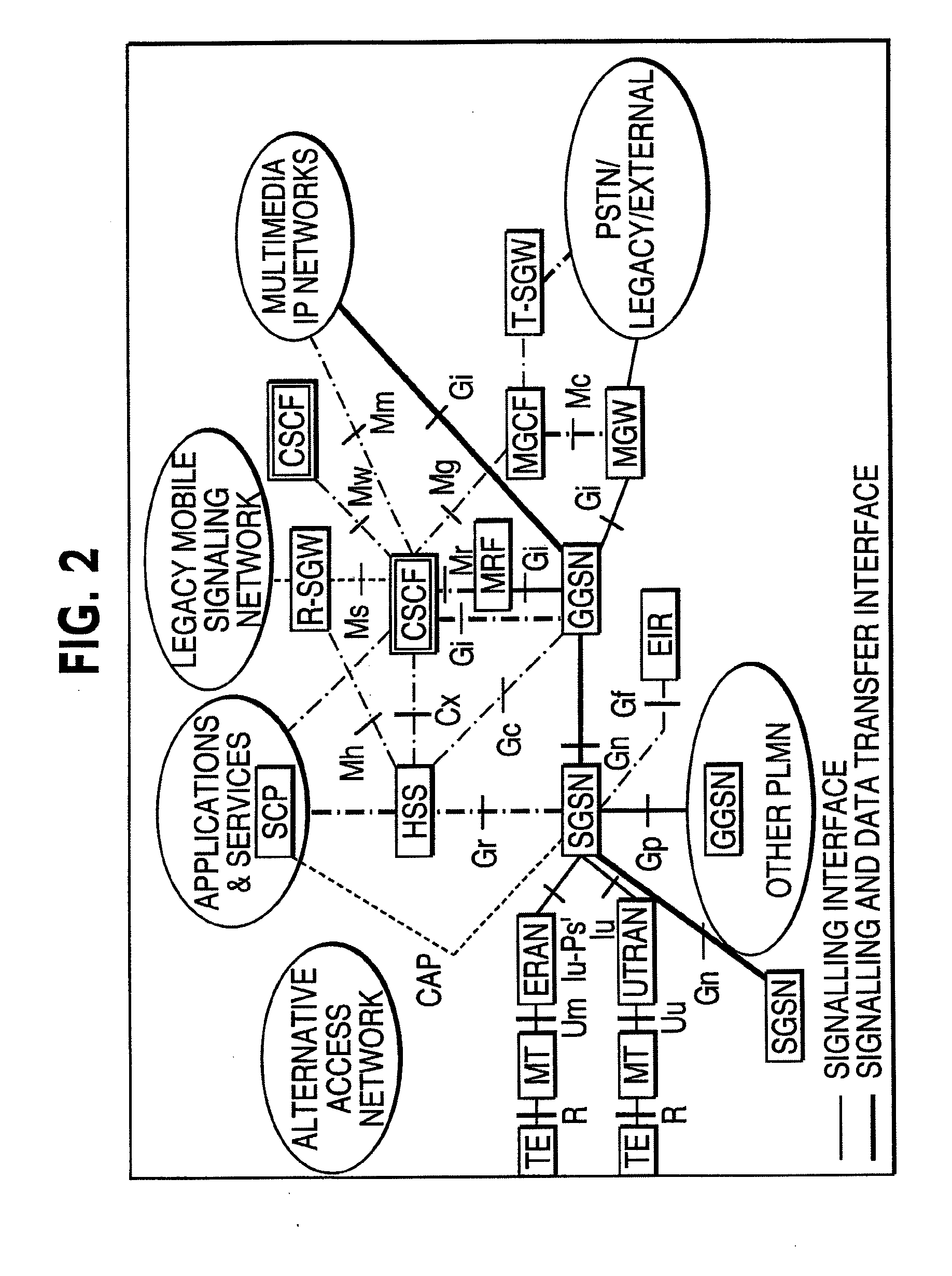
[0023]FIG. 1 is a block diagram of a typical 3rd generation Mobile IP Telephony network based on the UMTS standard. The detailed technical specifications for a UMTS network have been published by the 3rd Generation Partnership Project in Release 1999 (www.3gpp.org). The blocks in FIG. 1 represent different functionalities and do n...


PUM


Abstract

An emergency telephone call is supported and routed to a Public Safety Answering Point (PSAP) in an IP based packet switched wireless communications network. An activate PDP context request is sent from a user equipment to the network. A parameter in said activate PDP context request indicates that the PDP context will be used to transfer an emergency call. An activate PDP context accept message is returned from said support node to said user equipment. Said activate PDP context accept message acknowledges said activate PDP context request message and provides the address of a call state control function. A call setup request transferred to the call state control function includes the Service Area Identity (SAI). The call state control function selects a PSAP based, at least in part, on the SAI included in the call setup request and forwards the emergency call to the selected PSAP.

Description

CROSS-REFERENCE TO RELATED APPLICATIONS[0001]This application is a continuation-in-part of U.S. patent application Ser. No. 09 / 546,207 and of U.S. patent application Ser. No. 09 / 546,208, both of which were filed on Apr. 10, 2000 and which hereby have their disclosures incorporated by reference into this application.BACKGROUND[0002]1. Field of the Invention[0003]The present invention relates generally to methods and systems providing telephony communications through packet-switched communication networks. Particular aspects of the invention relate to location-based services in Internet Protocol (IP) based packet switched mobile communication networks, a method of making location-based services available to network subscribers when roaming between or within such communication networks, and the support and routing of emergency calls in such communication networks.[0004]2. Discussion of the Related Art[0005]Communications services have historically been provided over circuit-switched ne...

Claims


Application Information

Patent Timeline
Patent Type & Authority Applications(United States)
IPC IPC(8): H04W4/00H04B7/005H04L12/66H04W4/22H04L12/56H04W4/90H04B7/26H04L12/28H04W4/02H04W4/029H04W8/26H04W40/00H04W76/02H04W80/00H04W80/04
CPCH04W4/02H04W4/22H04W8/26H04W80/00H04W76/007H04W76/02H04W40/00H04W76/50H04W4/90H04W76/10H04L12/28H04W4/029
Inventor FACCIN, STEFANOHURTTA, TUIJARAJANIEMI, JAAKKOHUANG, HUAI HERMANKAUPPINEN, RISTOMUHONEN, JANNEVANTTINEN, VEIJOKALL, JANHAUMONT, SERGESYRJALA, JARI
Owner GOOGLE TECH HLDG LLC
Learn More