Cooling fan

Active Publication Date: 2010-03-18
MITSUBA CORP
View PDF4 Cites 24 Cited by
  • Summary
  • Abstract
  • Description
  • Claims
  • Application Information

AI Technical Summary

Benefits of technology

[0017]Consequently, it is possible to set the thickness of the blade on the side radially inner from the ring member thinner than that of the blade on the. side radially outer from the ring member. This can make the blade excellent in strength balanc

Problems solved by technology

In such a cooling fan with a ring member provided on the tips of the blades, the blades become heavy.
However, in the aforementioned conventional technique, since the blades are made thinner, when the cooling fan is rotated, the thinned blades flap.
This poses a problem of w

Method used


Image

  • Cooling fan
  • Cooling fan
  • Cooling fan

Examples


Example

[0023]1: COOLING FAN[0024]2: BOSS PORTION[0025]3: BLADE[0026]3a: BASE PORTION[0027]3b: TIP PORTION[0028]20: RING MEMBER

BEST MODE FOR CARRYING OUT THE INVENTION

[0029]Next is a description of an embodiment of this invention based on the drawings.

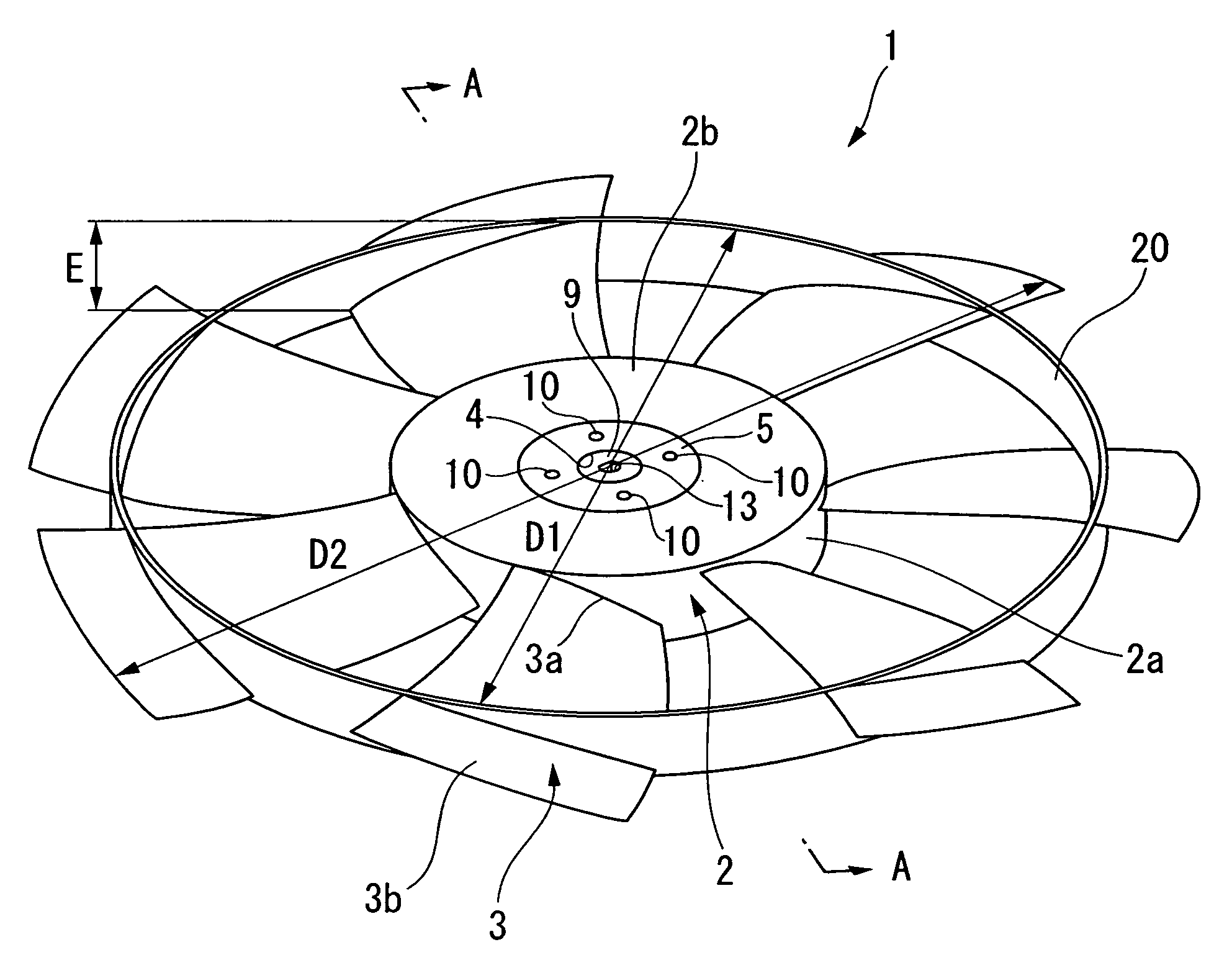
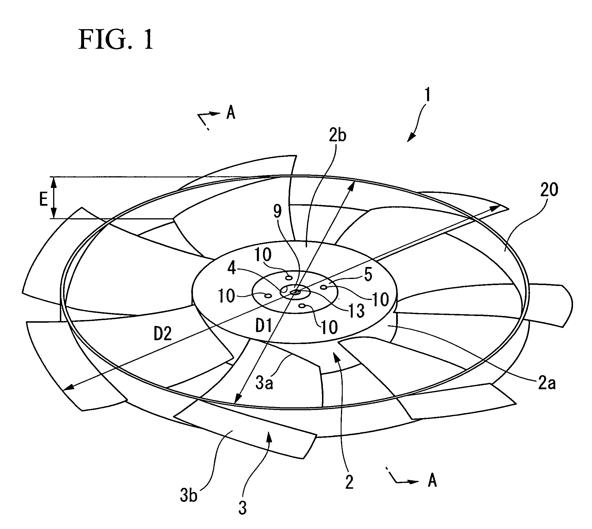
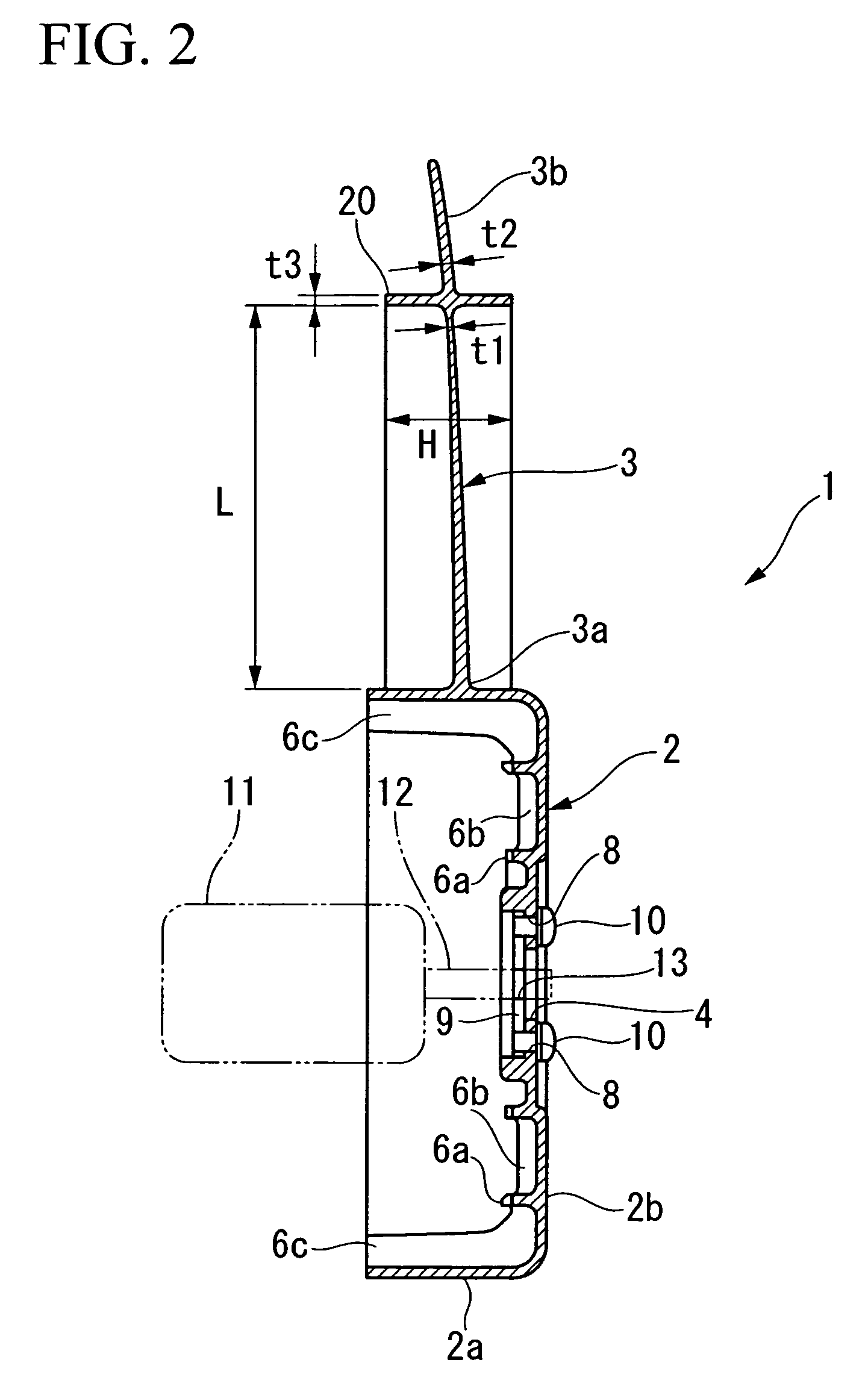
[0030]As shown in FIG. 1 to FIG. 3, a cooling fan 1 for an automobile radiator is an axial fan, including: a bottomed cylindrical boss portion 2 attached on a rotation shaft 12 of an electric motor 11; a plurality of (seven, in this embodiment) blades 3 provided on an outer circumferential surface of the boss portion 2, the blades 3 radiating in a radial direction, in which a cylindrical ring member 20 for connecting the blades 3 with each other is provided on a side radially inner from tips of the blades 3.

[0031]The boss portion 2 is made of: a circumferential wall 2a; and a bottom wall 2b. A coupling portion between the circumferential wall 2a and the bottom wall 2b, that is, an intersection ridgeline between the circumferential wall 2a and ...


PUM


Abstract

A cooling fan of the present invention includes: a bottomed cylindrical boss portion; and a plurality of blades provided on an outer circumferential surface of the boss portion, the blades radiating in a radial direction, in which a ring member for connecting the blades with each other is provided on a side radially inner from tips of the blades. According to the present invention, it is possible to provide a cooling fan capable of preventing the worsening of the noise characteristic and also of enhancing the versatility even if the blades are made thinner.

Description

TECHNICAL FIELD[0001]The present invention relates to a cooling fan for use in an automobile radiator and the like.[0002]Priority is claimed on Japanese Patent Application No. 2006-333037 filed on Dec. 11, 2006, the contents of which are incorporated herein by reference.BACKGROUND ART[0003]Conventionally, cooling fans for use in an automobile radiator and the like are often axial fans and diagonal fans. The cooling fans of these types are made of: a bottomed cylindrical boss portion that is rotated by a drive source such as an engine or an electric motor; and a plurality of blades provided on an outer circumferential surface of the boss portion, the blades radiating in a radial direction.[0004]By the way, there is known a cooling fan in which the tips of the blades are connected with each other by means of an annular ring member, to thereby improve the strength of the blades. In such a cooling fan with a ring member provided on the tips of the blades, the blades become heavy. Theref...

Claims


Application Information

Patent Timeline
IPC IPC(8): F04D29/38
CPCF04D29/325F04D29/668F04D29/666F04D29/326
Inventor OTA, HIDETAKEMAEKAWA, HIROHIKOYUICHI, KATAYAMA
Owner MITSUBA CORP
Why Eureka
Try Eureka