Systems and methods for joint replacement

a joint replacement and system technology, applied in the field of systems and methods for knee joint replacement, can solve the problems of insufficient accuracy, cost, room, and complex systems of current systems and methods, and achieve the effect of maximizing the sensitivity of the sensor

Inactive Publication Date: 2010-03-18
ORTHALIGN
View PDF5 Cites 137 Cited by
  • Summary
  • Abstract
  • Description
  • Claims
  • Application Information

AI Technical Summary

Benefits of technology

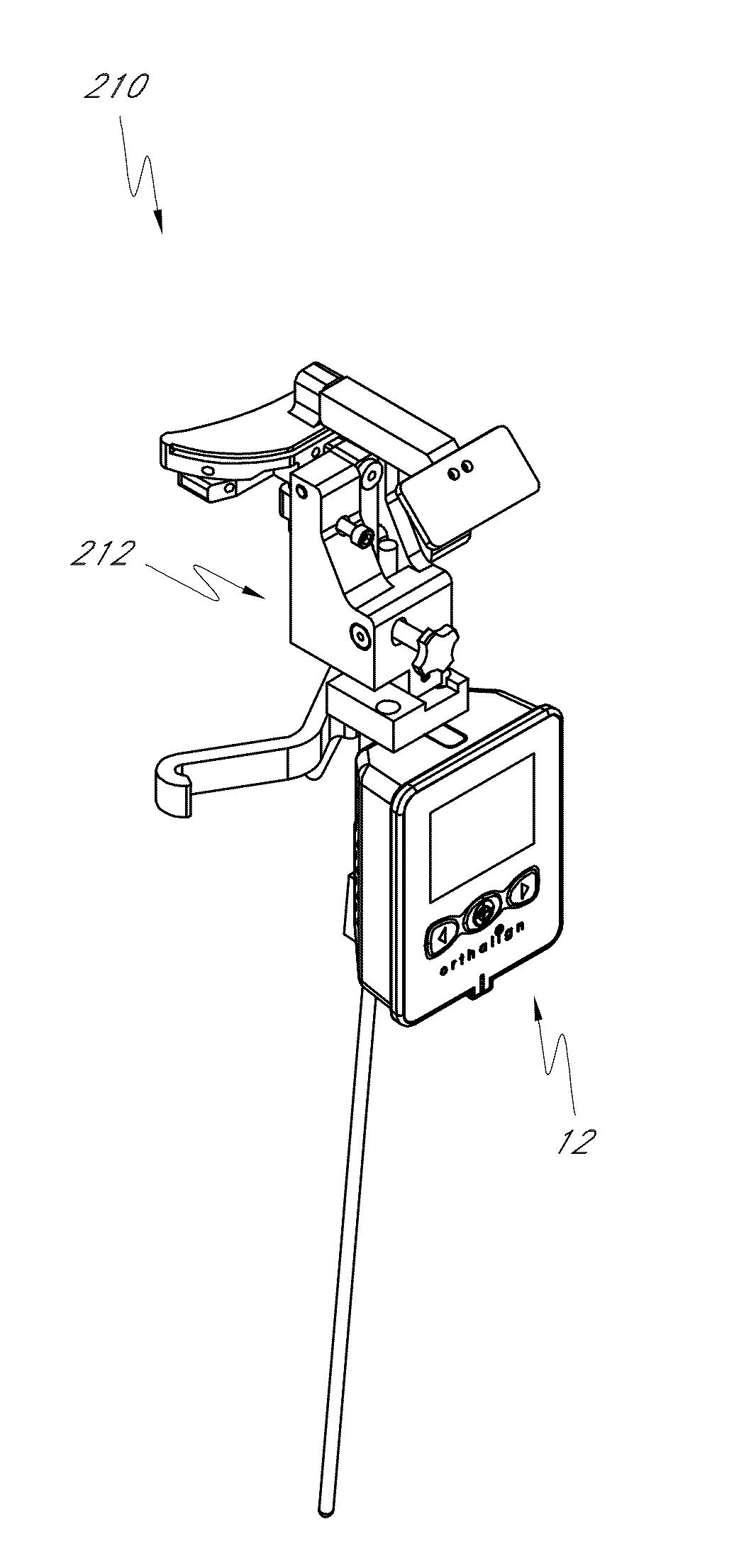
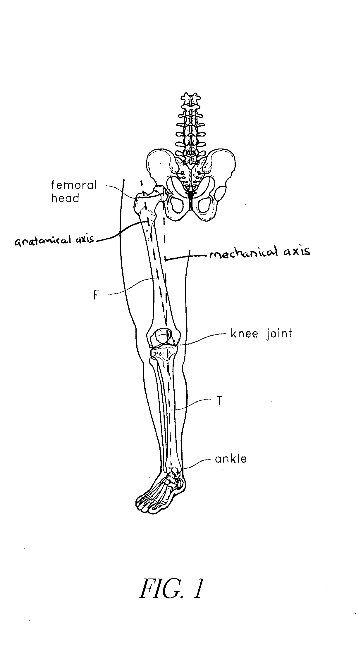
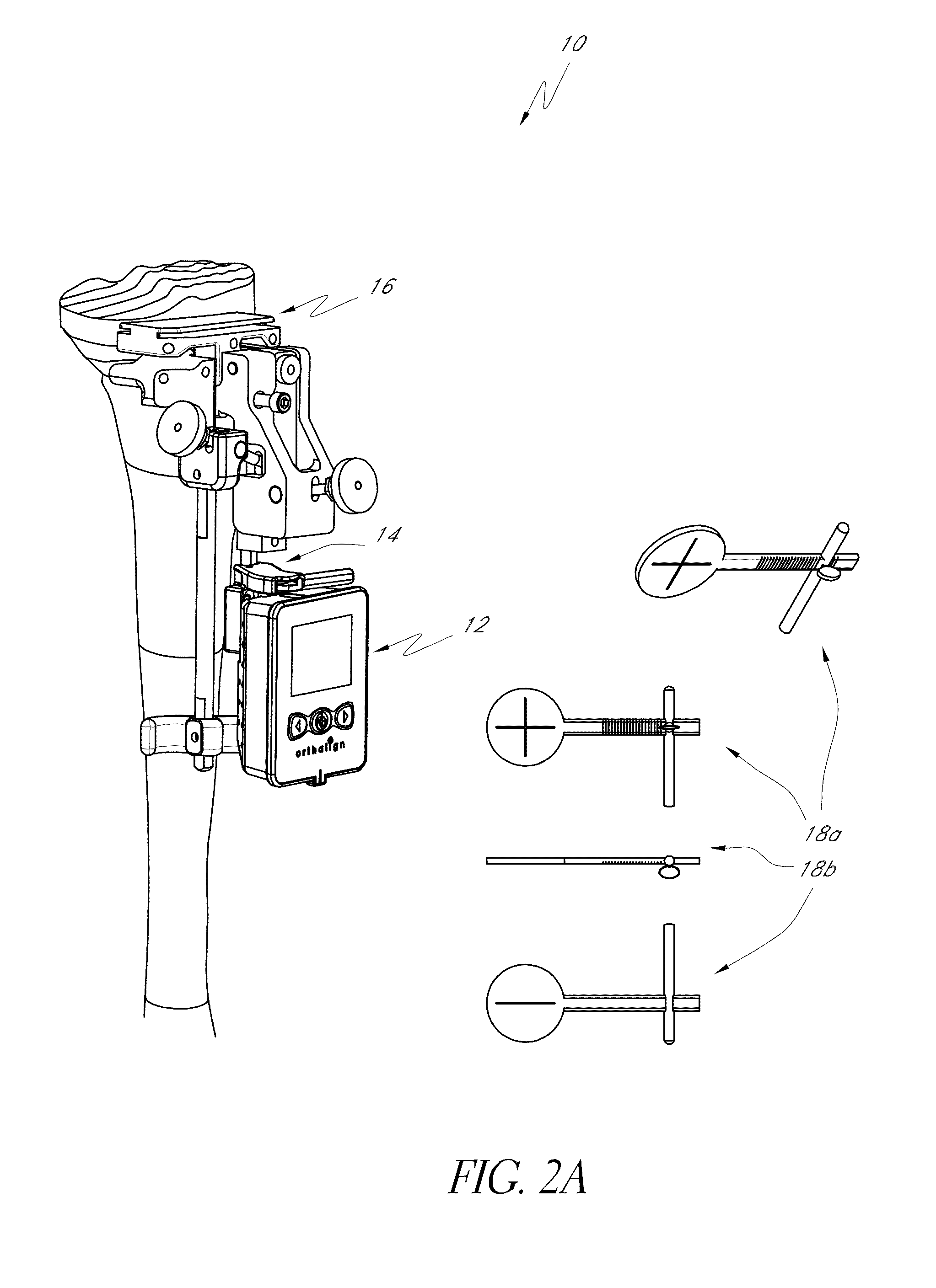
[0009]In accordance with at least one embodiment, a surgical orientation device for use in a total knee arthroplasty procedure having an associated three-dimensional coordinate reference system can comprise a portable housing configured to connect to a knee bone by way of one or more orthopedic fixtures, a sensor located within the housing, the sensor configured to monitor the orientation of the housing in the three-dimensional coordinate reference system, the sensor further configured to generate orientation data corresponding to the monitored orientation of the surgical orientation device, and wherein the sensor comprises a multi-axis accelerometer. The surgical orientation device can further comprise a display module configured to display one or more angle measurements corresponding to an offset from a flexion-extension angle or a varus-valgus angle of a mechanical axis of the knee joint, and wherein the sensor can be oriented relative to the housing at an acute angle to maximize the sensitivity of the sensor when coupled to a tibia or a femur.

Problems solved by technology

Current systems and methods often use expensive, complex, bulky, and / or massive computer navigation systems which require a computer or computers, as well as three dimensional imaging, to track a spatial location and / or movement of a surgical instrument or landmark in the human body.
These systems are used generally to assist a user to determine where in space a tool or landmark is located, and often require extensive training, cost, and room.
Where such complex and costly system are not used, simple methods are used, such “eyeballing” the alignment of rods with anatomical features, such as leg bones.
These simple methods are not sufficiently accurate to reliably align and place implant components and the bones to which such components are attached.
Accordingly, there is a lack of devices, systems and methods that can be used to accurately position components of prosthetic joints without overly complicating the procedures, crowding the medical personnel, and / or burdening the physician of health-care facility with the great cost of complex navigation systems.

Method used


Image

  • Systems and methods for joint replacement
  • Systems and methods for joint replacement
  • Systems and methods for joint replacement

Examples


Embodiment Construction

[0082]Although certain preferred embodiments and examples are disclosed below, it will be understood by those skilled in the art that the inventive subject matter extends beyond the specifically disclosed embodiments to other alternative embodiments and / or uses of the invention, and to obvious modifications and equivalents thereof. Thus it is intended that the scope of the inventions herein disclosed should not be limited by the particular disclosed embodiments described below. Thus, for example, in any method or process disclosed herein, the acts or operations making up the method / process may be performed in any suitable sequence, and are not necessarily limited to any particular disclosed sequence. For purposes of contrasting various embodiments with the prior art, certain aspects and advantages of these embodiments are described where appropriate herein. Of course, it is to be understood that not necessarily all such aspects or advantages may be achieved in accordance with any pa...


PUM


Abstract

Systems and methods for joint replacement are provided. The systems and methods include a surgical orientation device and at least one orthopedic fixture. The surgical orientation device and orthopedic fixtures can be used to locate the orientation of an axis in the body, to adjust an orientation of a cutting plane or planes along a bony surface, to distract a joint, or to otherwise assist in an orthopedic procedure or procedures.

Description

CROSS-REFERENCE TO RELATED APPLICATIONS[0001]This application claims benefit under 35 U.S.C. §119(e) to U.S. Provisional Patent Application No. 61 / 102,754, filed Oct. 3, 2008, U.S. Provisional Patent Application No. 61 / 135,863, filed Jul. 24, 2008, U.S. Provisional Patent Application No. 61 / 102,767, filed Oct. 3, 2008, U.S. Provisional Patent Application No. 61 / 155,093, filed Feb. 24, 2009, U.S. Provisional Patent Application No. 61 / 104,644, filed Oct. 10, 2008, U.S. Provisional Patent Application No. 61 / 153,268, filed Feb. 17, 2009, U.S. Provisional Patent Application No. 61 / 153,257, filed Feb. 17, 2009, U.S. Provisional Patent Application No. 61 / 153,255, filed Feb. 17, 2009, U.S. Provisional Patent Application No. 61 / 173,158, filed Apr. 27, 2009, U.S. Provisional Patent Application No. 61 / 187,632, filed Jun. 16, 2009, and U.S. Provisional Patent Application No. 61 / 173,159, filed Apr. 27, 2009, each of which is incorporated in its entirety by reference herein.BACKGROUND OF THE INVE...

Claims


Application Information

Patent Timeline
Patent Type & Authority Applications(United States)
IPC IPC(8): A61B17/58
CPCA61B17/155A61B17/154A61B2019/467A61B17/157A61B2090/067A61B17/1707A61B17/1764A61B34/20A61B2034/2048A61B34/25A61B17/7017
Inventor BORJA, SANTIAGO P.WALT, NICHOLAS VAN DER
Owner ORTHALIGN
Why Eureka
Try Eureka