
Cyclic code processing circuit, network interface card, and cyclic code processing method

a processing circuit and cyclic code technology, applied in the field of cyclic code computing circuits, can solve the problems of generation of cyclic codes, inability to produce correct computational results, and difficulty in achieving broader bandwidths, and achieve the effect of processing delay

Active Publication Date: 2010-03-18
NEC CORP
View PDF9 Cites 18 Cited by
  • Summary
  • Abstract
  • Description
  • Claims
  • Application Information

AI Technical Summary

Benefits of technology

[0047]It is an exemplary object of the present invention to provide a parallel cyclic code processing circuit which is capable of solving the problem in which “the circuit scale becomes larger and the processing delay increases as the parallel width of the input data increases”.

Problems solved by technology

If the electric signal processing processes are performed as a serial process, then it is difficult to achieve broader bandwidths because there are limitations on the processing rate.
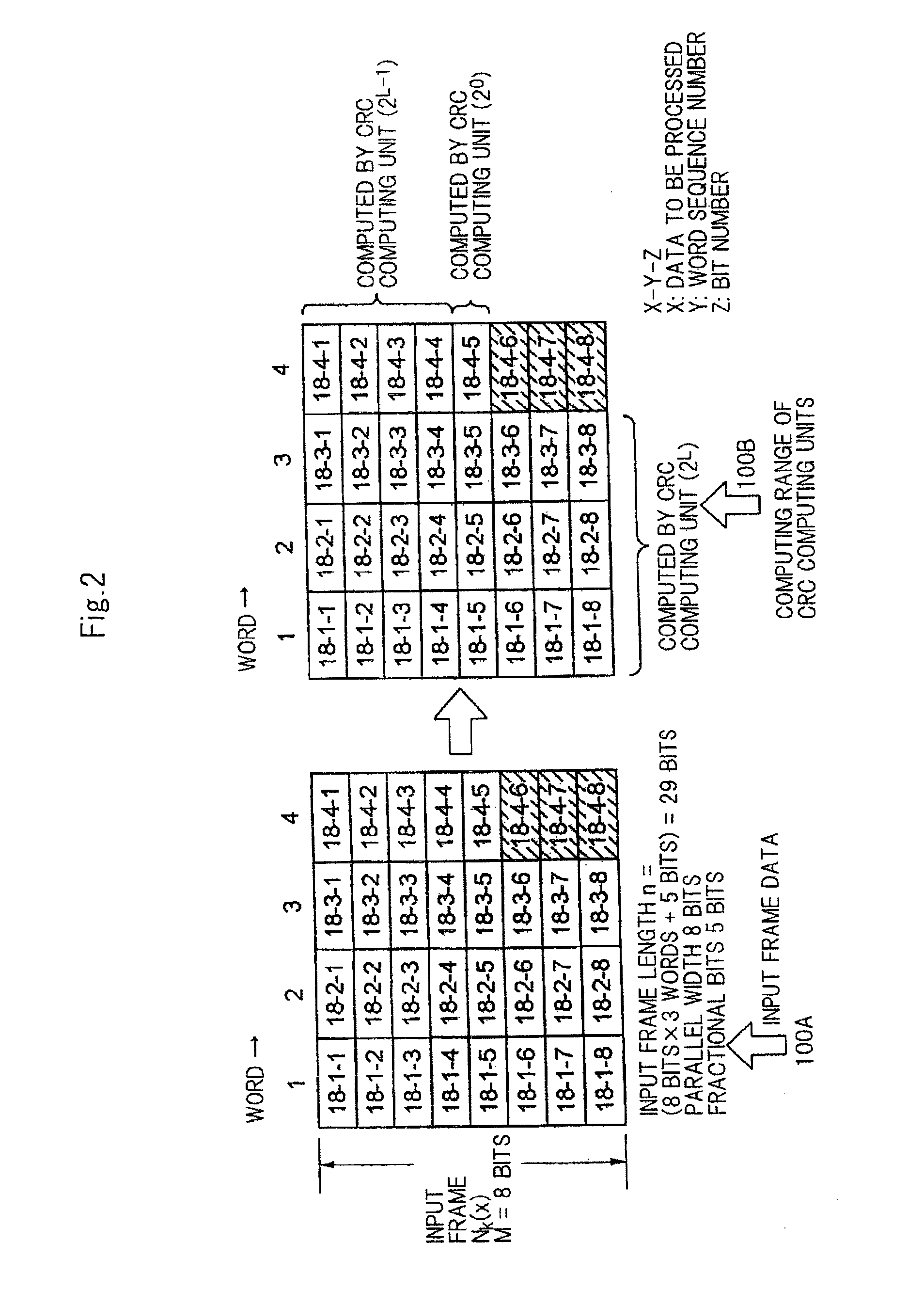
If parallelized frames including fractional bits are processed by a parallel cyclic code computing unit having a width of M bits, then even invalid bits other than the fractional bits fall in a cyclic code computational range, and correct computational results cannot be produced.
The same problem arises not only in the generation of a cyclic code, but also in the detection of errors based on a cyclic code.
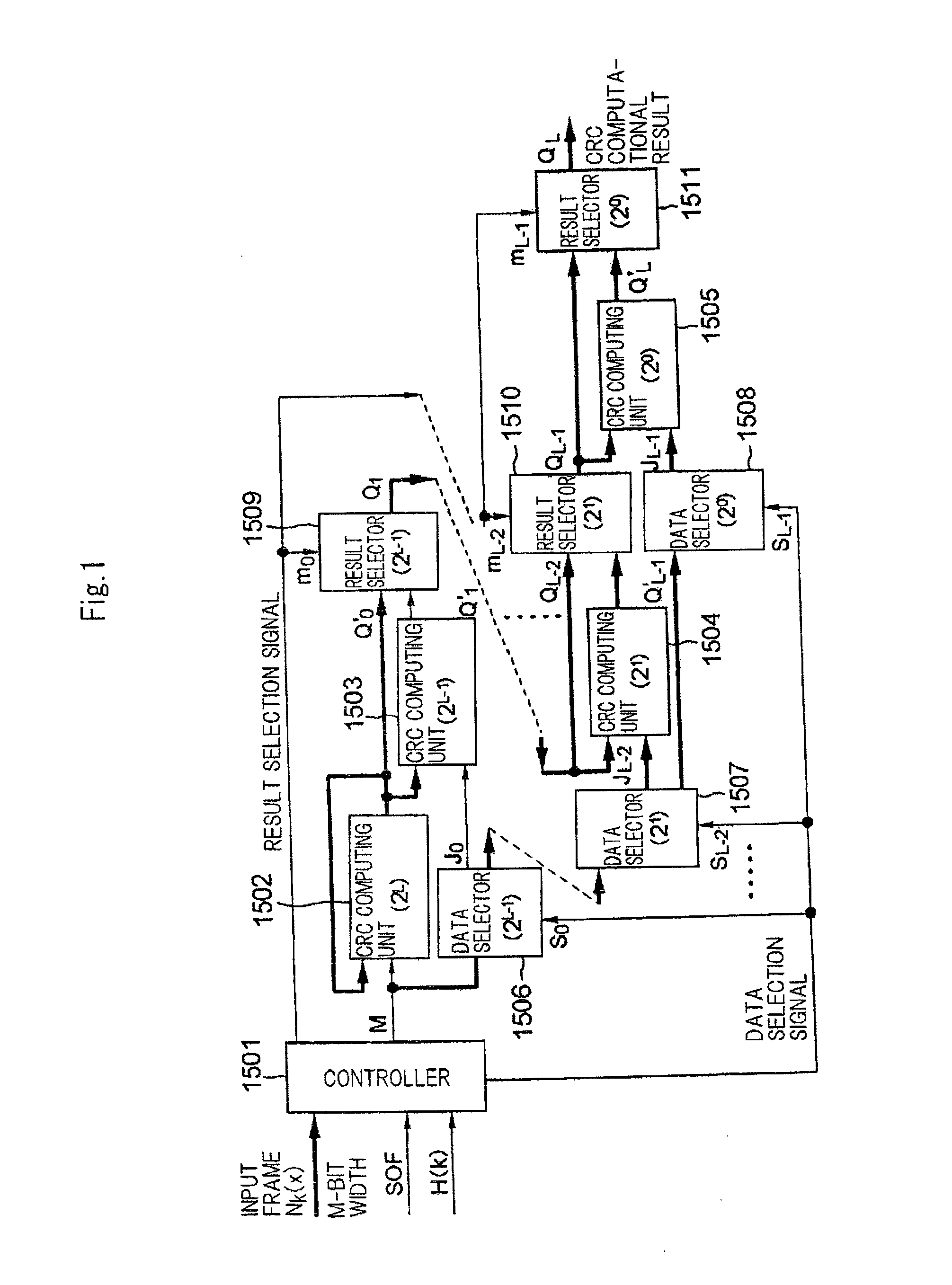
Furthermore, since CRC computing units 1502 through 1505, data selectors 1506 through 1508, and result selectors 1509 through 1511 are connected in cascade, the number of cascaded connections increases as the number M of parallel bits of the input data increases, resulting in an increase in the processing delay.

Method used


Image

  • Cyclic code processing circuit, network interface card, and cyclic code processing method
  • Cyclic code processing circuit, network interface card, and cyclic code processing method
  • Cyclic code processing circuit, network interface card, and cyclic code processing method

Examples


1st exemplary embodiment

(Configuration)

[0148]A first exemplary embodiment of the present invention will be described in detail below with reference to FIGS. 3 and 4.

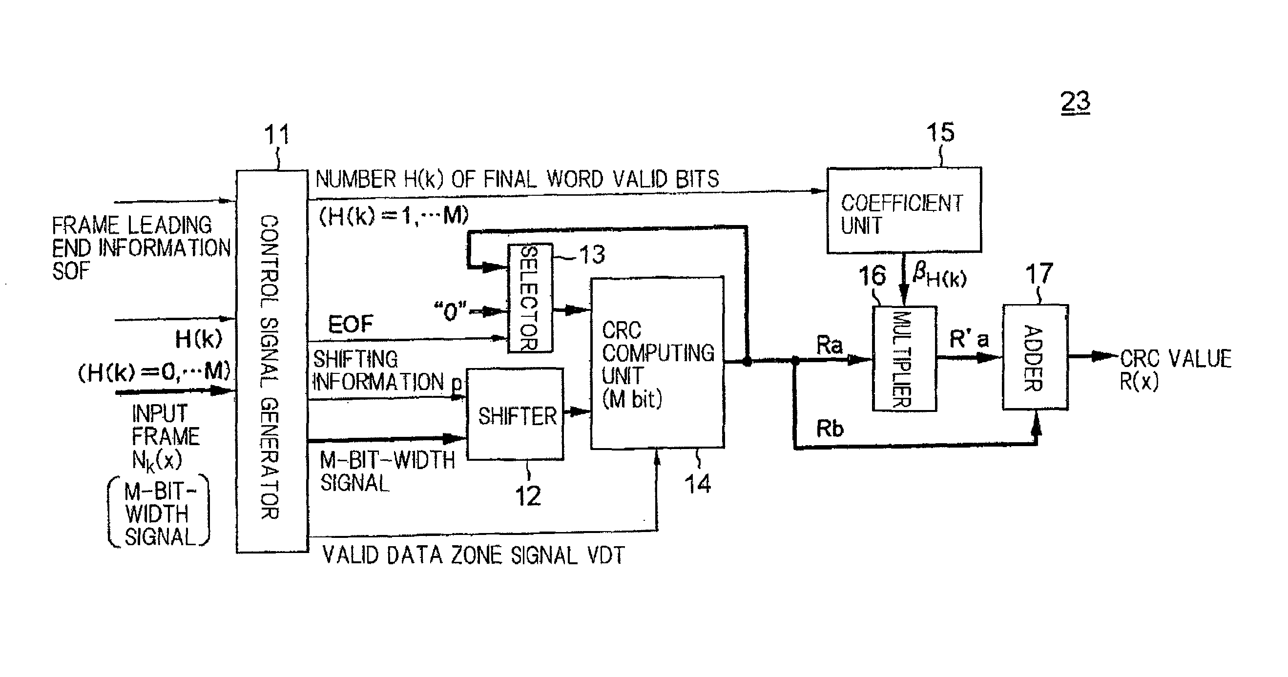
[0149]FIG. 3 is a block diagram of a transmitting function of network interface card (NIC) 28 according to a first exemplary embodiment of the present invention. Network interface card 28 is installed in a server apparatus or computer apparatus, not shown, and performs a process for transmitting and receiving frames.

[0150]Network interface card 28 comprises bus terminator 21, header allocator 22, parallel CRC code processor 23, FCS allocator 24, PCS (Physical Coding Sublayer) unit 25, and transmitter 26.

[0151]Bus terminator 21 is connected to a CPU bus in a server by a server connection bus. Transmitter 26 is connected to a transmission channel (at the right end of FIG. 3) for transmitting frames to an external circuit. Network interface card 28 allocates a frame header and an FCS value to a frame (an input frame, input data) input from the ser...


PUM


Abstract

Processor 23 calculates a first remainder, which is a remainder produced when an integral multiple data block is divided by a generator poly-nomial, by processing bits represented by the number of parallel bits in parallel. The integral multiple data block comprises bits positioned closer to the leading end of the input data than a final word which is a word at the tail end of the input data, in the case where a plurality of bits making up the input data are successively divided from the leading end with respect to each word which comprises the bits represented by the number of parallel bits. Processor 23 calculates a second remainder, which is a remainder produced when a final word valid data block made up of bits of the input data other than the integral multiple data block is divided by the generator polynomial. Processor 23 calculates an input data remainder, which is a remainder produced when the input data are divided by the generator polynomial, based on the first remainder and the second remainder.

Description

[0001]This application is based upon and claims the benefit of priority from Japanese Patent Application No. 2008-235124 filed in Japan Patent Office on Sep. 12, 2008, the contents of which are hereby incorporated by reference.BACKGROUND OF THE INVENTION[0002](1) Field of the Invention[0003]The present invention relates to a cyclic code computing circuit for generating and checking cyclic codes for use in a process of detecting errors in input data frames.[0004](2) Description of the Related Art[0005]In recent years, efforts have been in progress to achieve broader bandwidths for frame transmission rates in data communications technologies including 40 Gigabit Ethernet, and 100 Gigabit Ethernet, as specified by the IEEE 802 Committee, USA. “Ethernet” is a registered trademark (No. 1702119). Frame transmission processes for processing electric signals include a frame generation process for converting user data into frames and a frame reception process for extracting user data from fr...

Claims


Application Information

Patent Timeline
IPC IPC(8): H03M13/09G06F11/10
CPCH03M13/091H04L1/0061H04L1/0052
Inventor SHIGIHARA, MASAHIROTAKAMICHI, TORU
Owner NEC CORP
Learn More