Device customized home network top-level information architecture

a technology of information architecture and home network, applied in the field of devices and home networks, can solve the problems of providing static and command logic for controlling, remote control units cannot be used to command and control cd units, and remote control units cannot control and command only those home devices, etc., and achieve the effect of more reliabl

Inactive Publication Date: 2010-03-18
SAMSUNG ELECTRONICS CO LTD
View PDF58 Cites 8 Cited by
  • Summary
  • Abstract
  • Description
  • Claims
  • Application Information

AI Technical Summary

Benefits of technology

[0012]The present invention satisfies these needs. In one embodiment, the present invention provides a method and system for generating a user interface in a plurality of multiple devices connected to the network system for controlling devices that are currently connected to a network. In one version the network system includes a physical layer, wherein the physical layer provides a communication medium than can be used by devices to communicate with each other, and multiple devices connected to the physical layer, one or more of said multiple devices storing information including device information. A plurality of said multiple devices each including an agent adapted for: (a) obtaining information from devices currently connected to the network, said information including device information; (b) generating a user interface description in each of said one or more devices based at least on the obtained information, the user interface description in each device including at least one reference associated with the device information of each of said devices currently connected to the network; and (c) displaying one or more user interfaces each based on one of said one or more user interface descriptions, on one or more devices connected to the network capable of displaying a user interface, for user control of said devices that are currently connected to the network.

Problems solved by technology

One drawback associated with using the remote control unit to command and control home devices is that it provides static and command logic for controlling and commanding each home device.
Therefore, a particular remote control unit can only control and command those home devices for which it includes the necessary control and command logic.
For example, if a remote control unit comprises logic for controlling a television (TV), a video cassette recorder (VCR), and a digital video device (DVD), but not a compact disk (CD) unit, the remote control unit can not be used to command and control the CD unit.
In addition, as new home devices are developed, the remote control unit will not be able to control and command the new home devices that require control and command logic that was not known at the time the remote control unit was developed.
Further, typically a remote control unit can only be used to command and control those home devices that are within the signal range of the remote control unit.
Therefore, a user cannot use the remote control unit from a single location in the house to control and command home devices that are interconnected, but located in separate areas of the home.
If a user wishes to play a tape contained in the VCR located upstairs in the bedroom, on the TV located downstairs in the family room, the user cannot control and command both the TV and the VCR from a single location.
Another drawback associated with using remote control units is that known remote control units cannot control a plurality of diverse devices, and more particularly, cannot control a plurality of devices having different capabilities to communicate with each other in order to accomplish tasks or provide a service.
Further, conventional network systems do not provide a mechanism for software applications in different network devices to automatically communicate with one another in order to accomplish tasks without direct user command.
Further, if the device displaying the central user interface becomes unavailable, user control of the network is curtailed.
Another problem with the central / singular page is that every UI device must display the same page, and a scope is not provided for each manufacturer to generate its own UI look and feel nor alter the technology used in the UI device.
Nor can a UI builder tool obtain e-business icons from an external Web Portal.
Such a model cannot be standardized for industry use because a central / single UI device controls the UI.

Method used


Image

  • Device customized home network top-level information architecture
  • Device customized home network top-level information architecture
  • Device customized home network top-level information architecture

Examples


Embodiment Construction

Network Overview

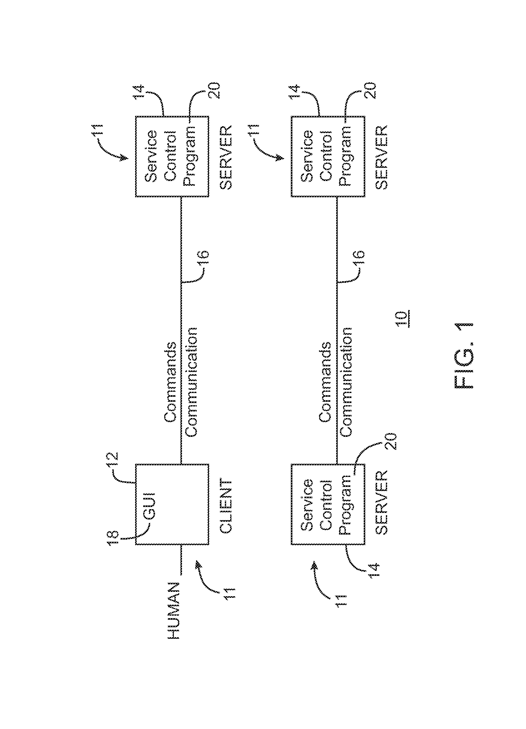
[0028]Referring to FIG. 1, in an embodiment of the present invention, a network 10 comprises multiple devices 11 including at least one client device 12 and at least one server device 14 interconnected via a communication link 16. The communication link 16 can include a 1394 serial bus providing a physical layer (medium) for sending and receiving data between the various connected home devices. The 1394 serial bus supports both time-multiplexed audio / video (NV) streams and standard IP (Internet Protocol) communications (e.g., IETF RFC 2734). In certain embodiments, a home network uses an IP network layer as the communication layer for the home network. However, other communication protocols could be used to provide communication for the home network. For example, the invention may be implemented using Function Control Protocol (FCP) as defined by IEC 61883, or any other appropriate protocol. Thus, a network may generally include two or more devices interconnected by ...


PUM


Abstract

A method and system for generating a user interface in a plurality of multiple devices connected to the network system for controlling devices that are currently connected to a network. A network system includes a physical layer, wherein the physical layer provides a communication medium than can be used by devices to communicate with each other, and multiple devices connected to the physical layer, one or more of said multiple devices storing information including device information. A plurality of said multiple devices each including an agent adapted for (a) obtaining information from devices currently connected to the network, said information including device information; (b) generating a user interface description in each of said one or more devices based at least on the obtained information, the user interface description in each device including at least one reference associated with the device information of each of said devices currently connected to the network; and (c) displaying one or more user interfaces each based on one of said one or more user interface descriptions, on one or more devices connected to the network capable of displaying a user interface, for user control of said devices that are currently connected to the network.

Description

CROSS-REFERENCES TO RELATED APPLICATIONS[0001]Applicants claim the benefit of U.S. Provisional Application No. 60 / 146,101 entitled “Network Architecture,” filed on Jul. 27, 1999, and U.S. Provisional Application No. 60 / 149,515 entitled “External Web Server Included in Home Network Top-Level User interface Description,” filed on Aug. 17, 1999, which applications are incorporated herein by reference.[0002]A portion of the disclosure of this patent document contains material which is subject to copyright protection. The copyright owner has no objection to the facsimile reproduction by anyone of the patent disclosure, as it appears in the Patent and Trademark Office patent files or records, but otherwise reserves all copyright rights whatsoever.FIELD OF THE INVENTION[0003]The present invention relates to the field of networks, and more particularly, to home networks having multi-media devices connected thereto.BACKGROUND OF THE INVENTION[0004]A network generally includes a communication...

Claims


Application Information

Patent Timeline
Patent Type & Authority Applications(United States)
IPC IPC(8): G06F15/177G06F3/14G06Q10/00G06F15/00G06F19/00H04L12/24H04L12/28H04L12/40H04L12/64H04L29/08H04N5/44H04N5/765
CPCH04L12/2803H04L69/329H04L12/2814H04L12/40117H04L41/0253H04L41/046H04L41/18H04L41/22H04L2012/2841H04L2012/2849H04L2012/285H04L67/16H04L67/36H04L67/025H04L67/12H04L67/02H04L12/2809H04L67/51H04L67/75H04L12/28
Inventor HUMPLEMAN, RICHARDWANG, DONGYAN
Owner SAMSUNG ELECTRONICS CO LTD
Why Eureka
Try Eureka