Method for Piecing a Yarn and Rotor Spinning Machine for Carrying Out the Method

Inactive Publication Date: 2010-03-25
SAURER SPINNING SOLUTIONS GMBH & CO KG
View PDF3 Cites 4 Cited by
  • Summary
  • Abstract
  • Description
  • Claims
  • Application Information

AI Technical Summary

Benefits of technology

[0017]The invention is therefore based on the object of providing a method for piecing the yarn, by means of which the parameterisa

Problems solved by technology

The very complex process for determining the optimal piecing parameters until now has had to be carried out after every batch change and every change of spinning parameters, such as, for example, a change in the draft, the twist factor, the rotor speed and the like.
This task is made more difficult when spinning fine yarns with high yarn counts.
In this case, a certain delay occurs in reaching the required fiber flow and possibly causes a diameter deviation after the piecer.
Apart from the follow-up movement of the fiber flow after switching off the feed and the delayed starting up after switching on the feed, the fiber flow can also react with a delay when increasing the feed speed.
This can lead to diameter fluctuations of the yarn occurring after the piecer.
In the case of staple length distributions of natural fibers, which correspondingly fluctuate this leads in

Method used


Image

  • Method for Piecing a Yarn and Rotor Spinning Machine for Carrying Out the Method
  • Method for Piecing a Yarn and Rotor Spinning Machine for Carrying Out the Method
  • Method for Piecing a Yarn and Rotor Spinning Machine for Carrying Out the Method

Examples


Example

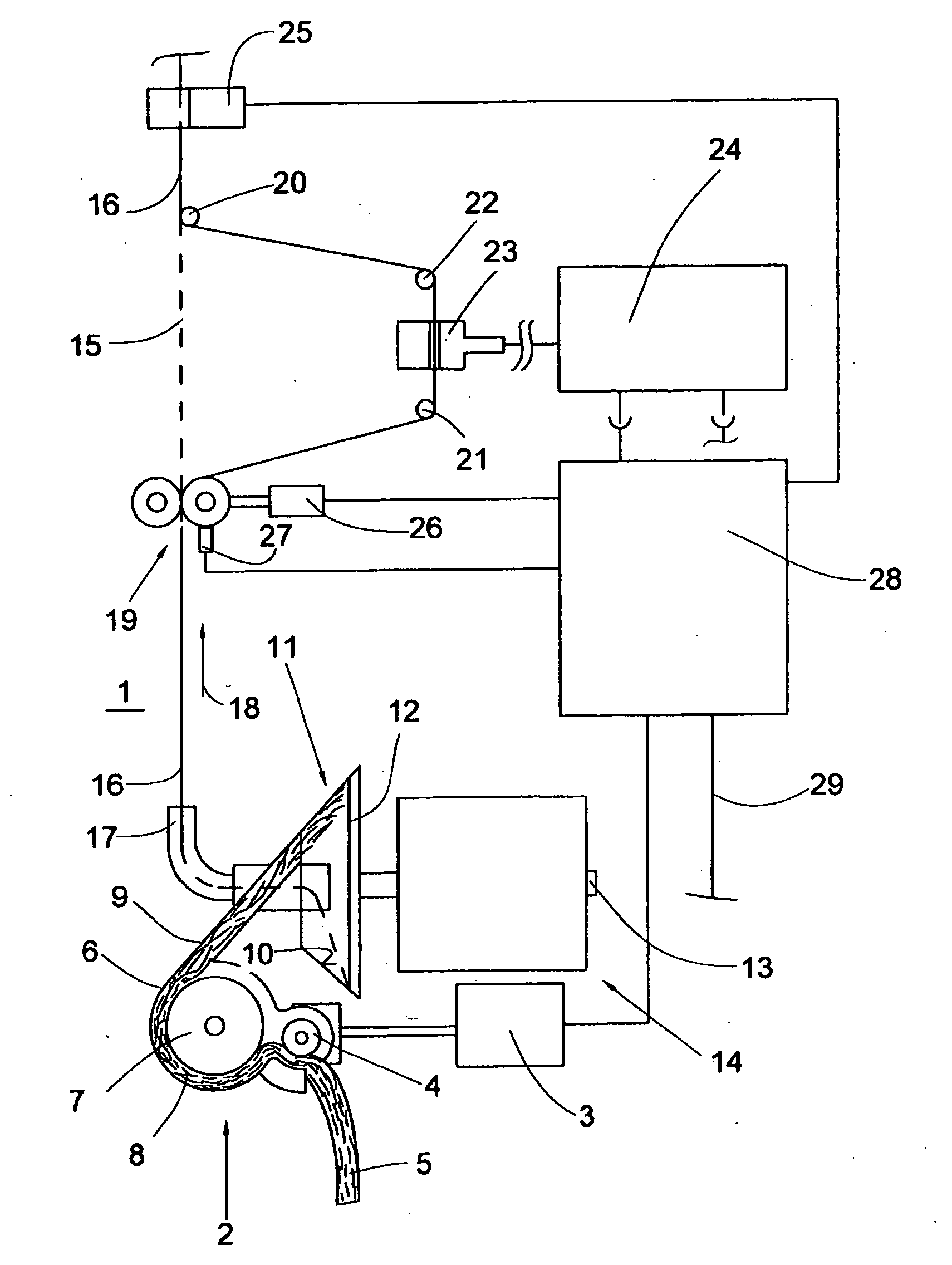
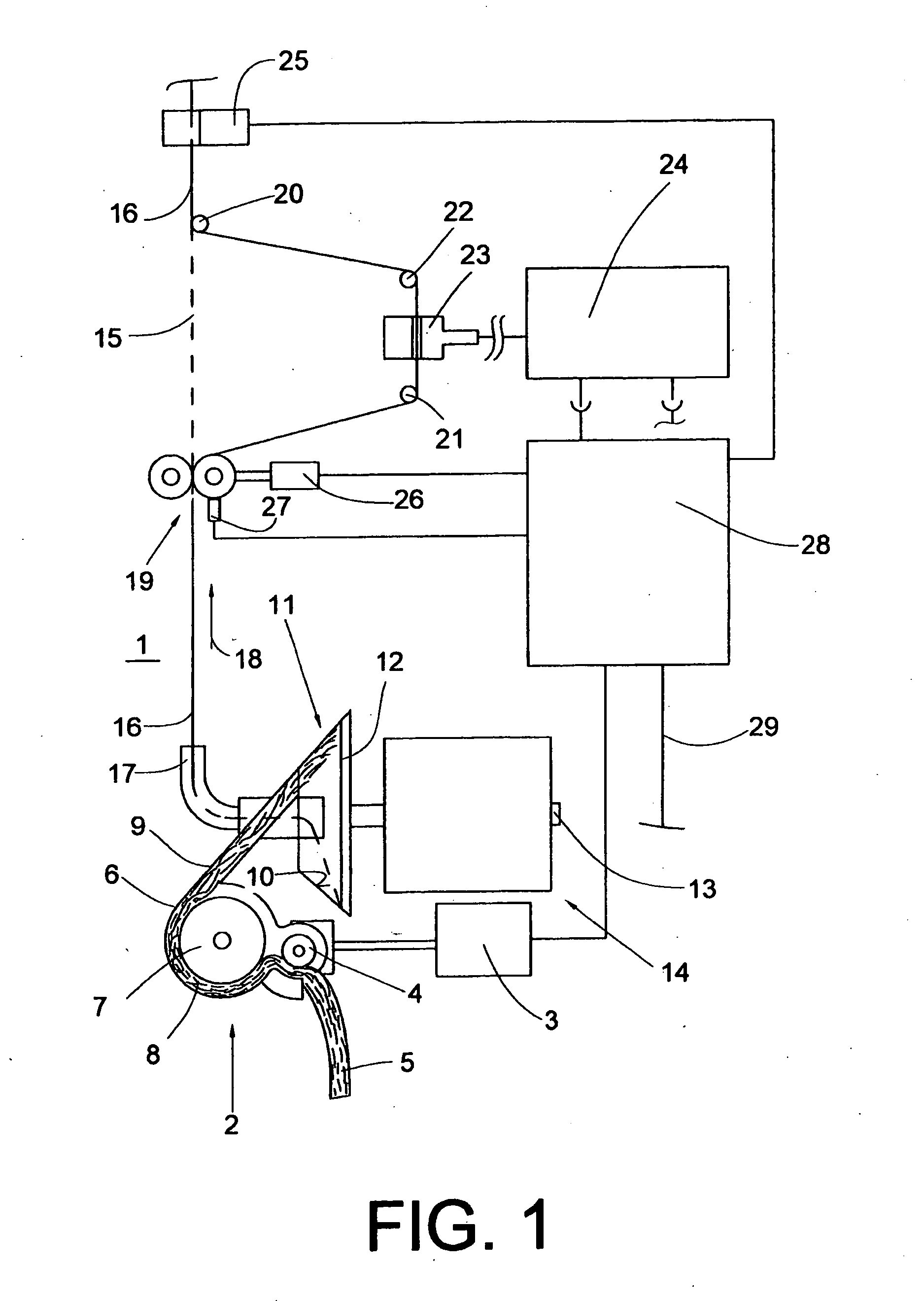
[0041]FIG. 1 schematically shows a side view of one half of an open-end rotor spinning machine producing cross-wound bobbins.

[0042]Rotor spinning machines of this type have, as known, between their end frames (not shown), a large number of similar spinning stations 1, the components of which are driven by a single motor. The spinning station 1 has an opening device 2, into which a fiber band 5 is introduced by means of the feed roller 4. The feed roller 4 is driven by a continuously adjustable feed motor 3. The fiber band 5 is fed to an opening roller 7 rotating in the housing 6 and driven by a single motor and which opens the fiber band 5 supplied into individual fibers 8.

[0043]The separated fibers 8 arrive through the fiber guide channel 9 onto the conical slip face 10 of a spinning rotor and from there into the fiber collecting groove 12. From the fiber collecting groove 12, the spun yarn 16 is drawn through the fiber draw-off tube 17 in the direction of the arrow 18 with the aid...


PUM

PropertyMeasurementUnit
Fractionaaaaaaaaaa
Lengthaaaaaaaaaa
Diameteraaaaaaaaaa

Abstract

A method for piecing a yarn at a rotor spinning machine comprising plural spinning stations, wherein more than five piecers are successively produced in a measuring phase and coordinates of measurement values and associated measurement values from individual measurements of the piecers are evaluated for averaging and determining a fiber band function taking into account a drafting reduced for the measurement values, which reflects the fiber flow behaviour in the form of the respective fiber band quantity supplied to the rotor as a function of the transport path of the fiber band feed. The speed of the fiber band feed is controlled in a delayed manner from the run-up of the yarn draw-off, dependent on the rotor speed, by the fiber band function, such that the fiber shortfall quantity being produced from the fiber band function is compensated by dynamic feed addition with respect to height and length.

Description

CROSS-REFERENCES TO RELATED APPLICATIONS[0001]This application claims the benefit of German patent application 10 2005 059 078.0, filed Dec. 10, 2005, and corresponding International PCT Application No. PCT / EP2006 / 010502, each herein incorporated by reference.BACKGROUND OF THE INVENTION[0002]The present invention relates to a method for piecing a yarn at a rotor spinning machine and to a rotor spinning machine for carrying out such method.[0003]With increasing demands on the yarn production process, ever higher demands are also made on the production of piecers. The process of forming piecers after yarn interruptions, the piecing, is carried out at the individual spinning stations of the open-end rotor spinning machines, generally by a piecing unit travelling along the spinning machine, the so-called piecing carriage. The piecing process is controlled by means of a piecing program.[0004]The quality of piecers with regard to their visual appearance and strength is decisively influenc...

Claims


Application Information

Patent Timeline
IPC IPC(8): D01H4/50D01H13/32
CPCD01H13/32D01H4/50
Inventor LASSMANN, MANFRED
Owner SAURER SPINNING SOLUTIONS GMBH & CO KG
Why Eureka
Try Eureka