
Transmission device having at least one shift element which can be actuated by means of an actuator arrangement which has at least one electrical component

a technology of transmission device and shift element, which is applied in the direction of mechanical equipment, inductance, transportation and packaging, etc., can solve the problems of only being able to make needing available unused shaft areas, so as to avoid additional costly steps and save spa

Active Publication Date: 2010-03-25
ZF FRIEDRICHSHAFEN AG
View PDF4 Cites 62 Cited by
  • Summary
  • Abstract
  • Description
  • Claims
  • Application Information

AI Technical Summary

Benefits of technology

[0011]The very first embodiment of the invention and the following alternatives of this inventive transmission device allow, in a simple state of the art, the possibility of combining an electric component, needed to operate a switching element actuator, with the transmission shaft resulting in a very compact and also space saving configuration of all the different elements in the transmission system.
[0012]According to the invention, the transfer of electric energy and / or data between elements and components, which are mounted to the transmission housing, and electric elements needed for operation of at least one of the switching elements of the designated actuator offers, in a simple way, the opportunity to make use of readily available space, in the area of the gear shaft within of the existing transmission system, by placing one electric component needed to activate the switching element, also avoiding additional costly steps in the construction of the transmission to accommodate at least one switching element.

Problems solved by technology

Since neither the width of the bearings of the idle gear wheels located on the shaft nor the switching elements space requirements can be altered, and the directional guidance of the activating force through the shaft is very limited, the internal activation of the switching elements of the shaft has to be achieved in areas which are not functionally utilized by the idle gear wheels or the switching elements.
As a result, available unused areas of the shaft are needed which can only be made available by extending the length of the shaft.

Method used


Image

  • Transmission device having at least one shift element which can be actuated by means of an actuator arrangement which has at least one electrical component
  • Transmission device having at least one shift element which can be actuated by means of an actuator arrangement which has at least one electrical component

Examples


Embodiment Construction

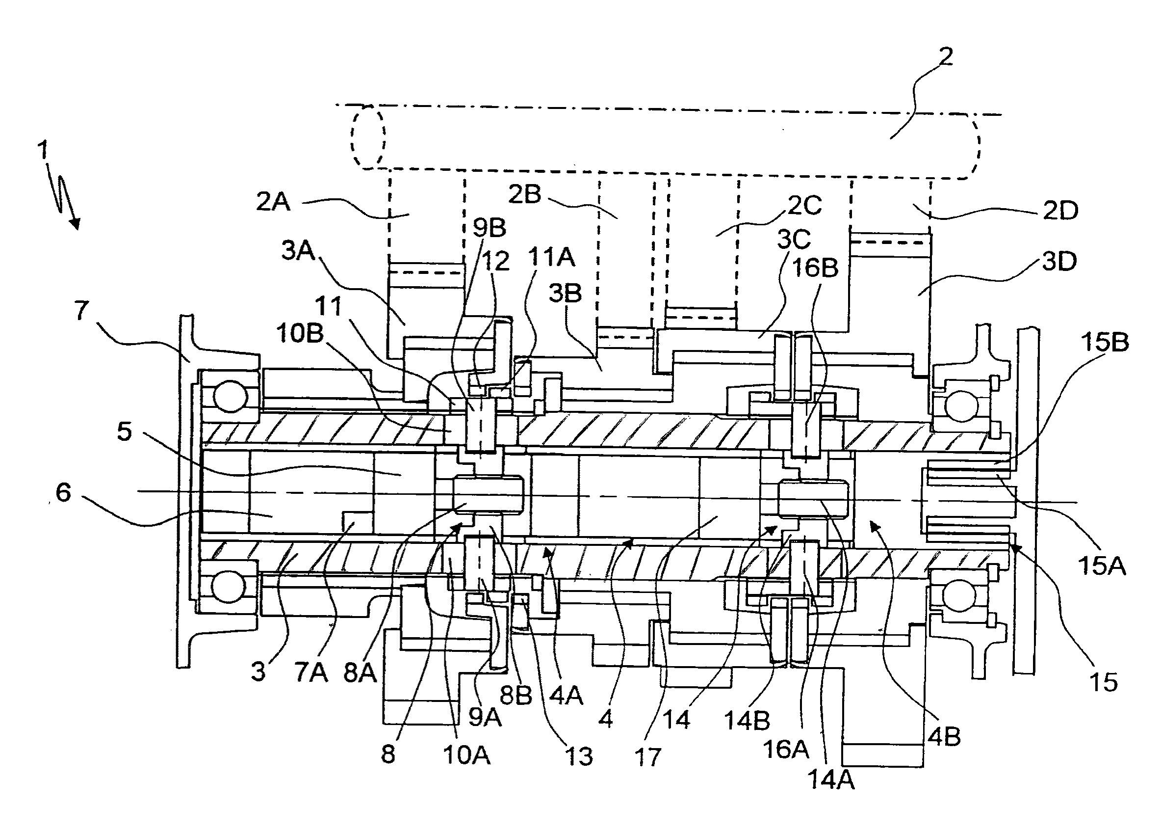
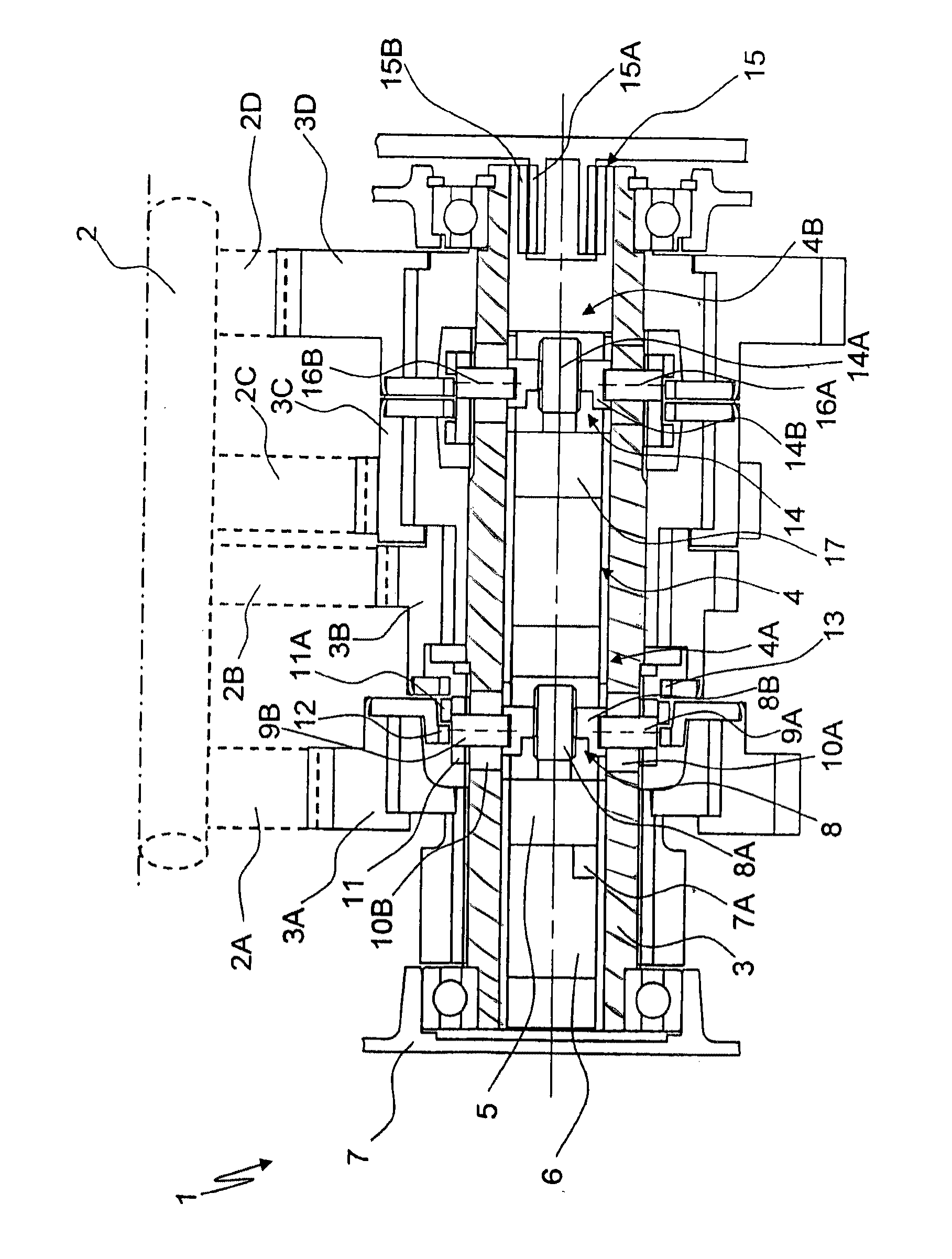
[0015]The shown FIGURE is a part of a transmission system 1, shown as an intermediate transmission configuration and shown in a longitudinal sectional view, presenting a transmission main shaft 2 and parallel to herewith a structure of the countershaft 3. Several gear wheels 2A to 2D are mounted on the transmission main shaft 2 and arranged as fixed gear wheels which interconnect with several rotatable idle gear wheels 3A to 3D supported on the countershaft 3. Idle gear wheels 3A and 3B can be engaged by way of a first switching device 4A of the actuator 4, while the idle gear wheels 3C and 3D can be engaged via a second switching device 4B of the actuator 4 so to become connected with countershaft 3 in a rotationally fixed manner.

[0016]The switching devices 4A and 4B basically have the same construction and configuration which is why the following specification focuses mainly on the switching device 4A only.

[0017]The switching device 4A is equipped with an electric actuator 5, whic...


PUM


Abstract

A transmission device (1) having a switching element, which is actuated by at least one electric component (5, 17) which is part of an actuator (4). The electric actuator component is linked to a countershaft (3) of the transmission and rotates at the speed of countershaft (3) during operation, and is functionally connected through an electric transformer rotary transformer device (15) with further enclosure mounted components of the transmission device (1). Via the transformer device (15), electric energy and / or data can be exchanged, through collector ring contacts, using inductive or capacitive coupling between the enclosure mounted components of transmission device (1) and at least one electric actuator component (5, 17) which is linked with the countershaft (3).

Description

[0001]National Stage filing of PCT / EP2007 / 060457 filed Oct. 2, 2007 which claims priority form German Application No. 10 2006 049 275.7 filed Oct. 19, 2006.FIELD OF THE INVENTION[0002]The invention describes a transmission device incorporating a shifting element being operated and initiated through an actuator configuration with at least one electrical element.BACKGROUND OF THE INVENTION[0003]Known in the art is an intermediate gear transmission such as a double clutch transmission, automatic shift transmissions, manual shift transmissions, or the like. These are generally configured and built by mounting rotating gear wheels on a shaft which are interconnecting with fixed gear wheels on an additional shaft, forming the so called gear wheel pairing. Through the interchangeable, fixed connections with the wheels which rotate on the shaft, the pairing of different gear shift positions in the intermediate transmission and its related flow of force in the intermediate transmission can b...

Claims


Application Information

Patent Timeline
IPC IPC(8): F16H61/32F16H63/30
CPCF16H61/32F16H63/304Y10T74/19251F16H2063/3063Y10T74/2003F16H2061/005F16H63/30H01F38/14H01F38/18
Inventor REISCH, MATTHIASMOHR, MARKDREIBHOLZ, RALF
Owner ZF FRIEDRICHSHAFEN AG
Learn More