Low power image sensor adjusting reference voltage automatically and optical pointing device comprising the same

Inactive Publication Date: 2010-03-25
SILICON COMM TECH
View PDF3 Cites 23 Cited by
  • Summary
  • Abstract
  • Description
  • Claims
  • Application Information

AI Technical Summary

Benefits of technology

[0057]An aspect of the present invention provides a low power image sensor in which a preprocessor that occupies a relatively large chip area and consumes relatively much power is not needed, so that a cost of an optical pointing image sensor is largely reduced and the power consumption is minimized.
[0058]Another aspect of the present invention provides a low power image sensor in which an A/D converter is replaceable with a simple comparator, so that the chip area can decrease to reduce the cost and power consumed in the A/D conver

Problems solved by technology

However, it is nearly impossible to determine the reference voltage of the simple comparator such

Method used


Image

  • Low power image sensor adjusting reference voltage automatically and optical pointing device comprising the same
  • Low power image sensor adjusting reference voltage automatically and optical pointing device comprising the same
  • Low power image sensor adjusting reference voltage automatically and optical pointing device comprising the same

Examples


Embodiment Construction

[0073]Below, technical configurations for realizing the invention will be described in more detail with reference to accompanying drawings.

[0074]The present invention may, however, be embodied in different forms and should not be constructed as limited to the embodiments set forth herein. Rather, these embodiments are provided so that this disclosure will be through and complete, and will folly convey the scope of the invention to those skilled in the art.

[0075]I. Configuration and Function of Low Power Image Sensor

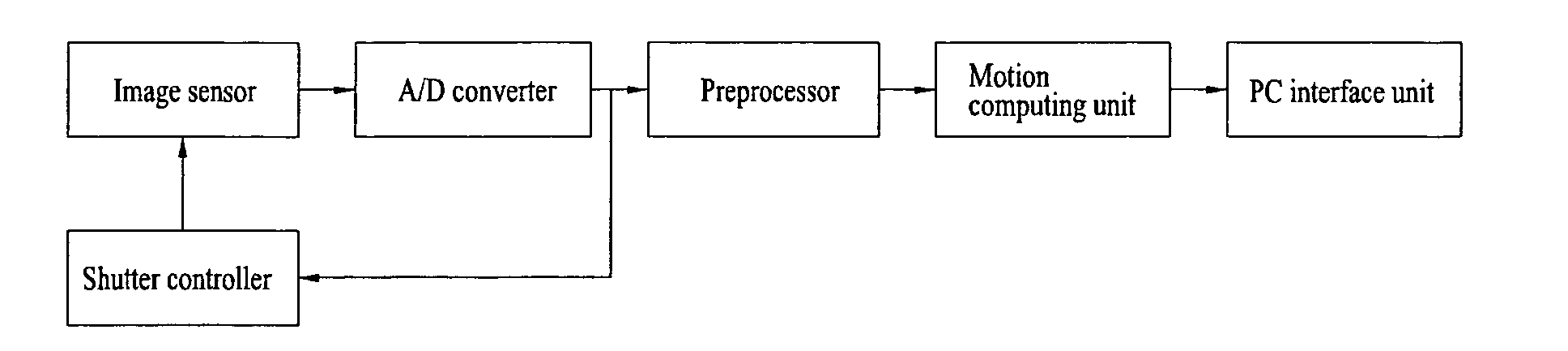
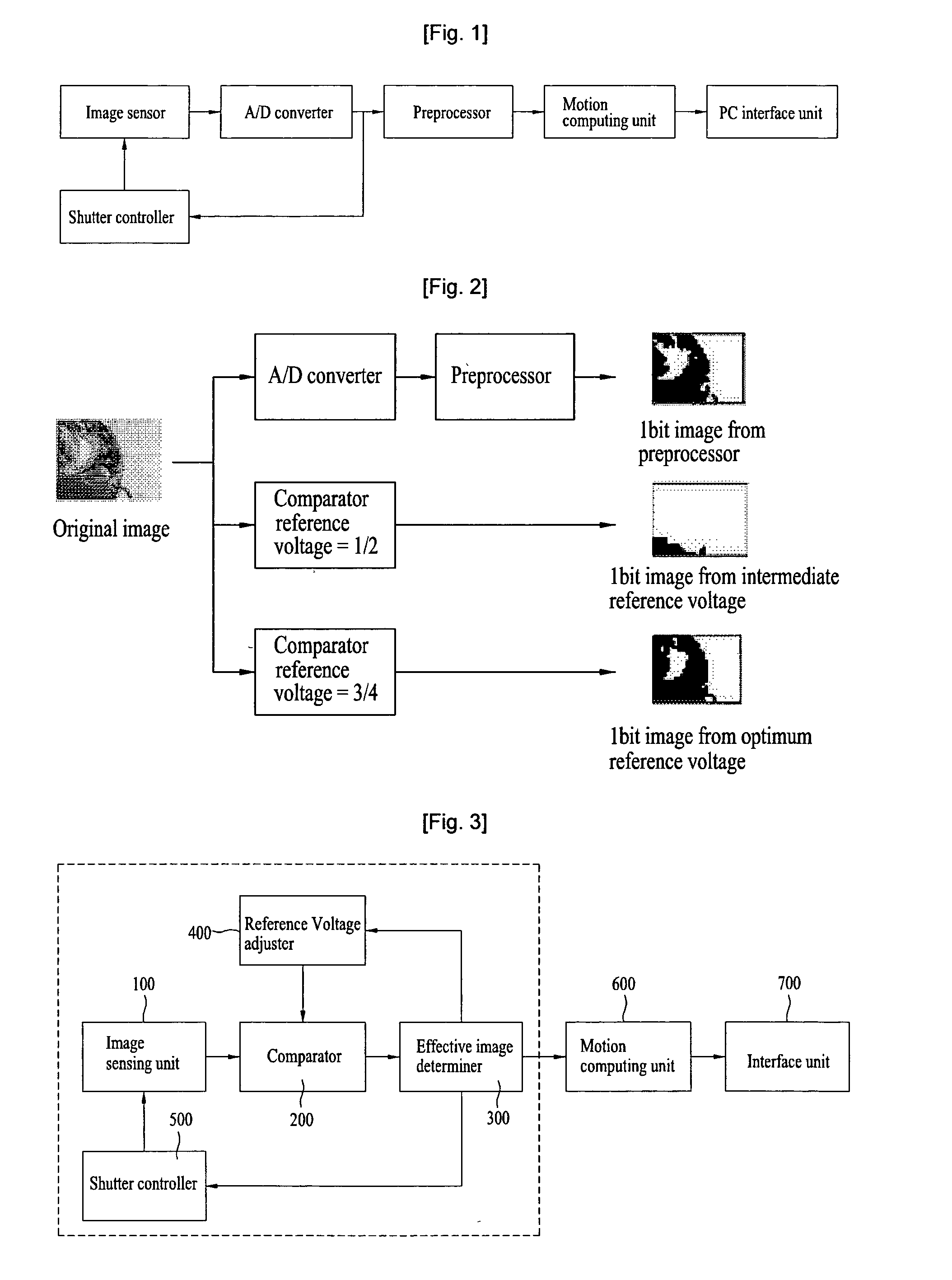
[0076]To overcome the foregoing limits of the conventional technologies, the present invention newly proposes a low power image sensor of which voltage is automatically adjusted, and which does not need an A / D converter and a preprocessor of an image signal processing chip for an optical mouse or a finger mouse, thereby providing an image processing chip that decreases in a cost and consumes low power.

1. Configuration

[0077]According to an exemplary embodiment of the inven...


PUM


Abstract

The low power image sensor includes: an image sensing unit which senses light from an object, converts the light into an electric signal, and outputs the electric signal; a comparing unit which receives an electric signal from the image sensor, compares a voltage level of the electric signal with a reference voltage, and outputs an image signal as a 1 bit signal per pixel; and an effective image adjuster which compares bit value distribution of an image signal output from the comperator with a preset effective range, and adjusts the effective image to output an effective image. Further, an optical pointing device includes: an image sensor which senses light from an object and outputs an image signal; and a motion computing unit which receives the image signal and compares before and after images to calculate a motion vector.

Description

PRIORITY CLAIM[0001]The present application is a National Phase entry of PCT Application No. PCT / KR2007 / 005806, filed Nov. 19, 2007, which claims priority from Korean Application Number 10-2006-0114048, filed Nov. 17, 2006, Korean Patent Application No. 10-2007-0013504, filed Feb. 9, 2007, and Korean Patent Application No. 10-2007-0110986, filed on Nov. 1, 2007, the disclosures of which are hereby incorporated by reference herein in their entirety.TECHNICAL FIELD[0002]The present invention relates to a low power image sensor adjusting a reference voltage and an optical pointing device having the same, and more particularly to a low power image sensor adjusting a reference voltage automatically to output a reliable 1 bit image signal proper for motion computation and an optical pointing device capable of computing before and after images output from the image sensor to effectively estimate a motion or a click.BACKGROUND ART[0003]The present invention is related to an optical pointing...

Claims


Application Information

Patent Timeline
IPC IPC(8): G06F3/033H04N5/335G06F3/0354H04N5/3745
CPCG06F3/03542G06F3/0304H04N5/37455H04N5/2352H04N23/72H04N25/772
Inventor KIM, SUKISUNG, JOON JEAPARK, HEE JUSHIN, JI HOON
Owner SILICON COMM TECH
Why Eureka
Try Eureka