Light transmission touch panel

a touch panel and light transmission technology, applied in the field of light transmission touch panels, can solve the problems of scratching, exposure and ito etching, and achieve the effects of high transmittance, simplified structure, and high transmittan

Inactive Publication Date: 2010-03-25
RITFAST CORP
View PDF8 Cites 98 Cited by
  • Summary
  • Abstract
  • Description
  • Claims
  • Application Information

AI Technical Summary

Benefits of technology

[0011]An aspect of the present invention is to provide a light transmission touch panel with high transmittance. The electrode cells with different polarities of the touch panel are formed during the same process, and do not overlap each other. Furthermore, the total area of the insulation layer of the touch panel covering the substrate is minimized. Therefore, the touch panel has high transmittance due to its simplified structure.
[0012]Another aspect of the present invention is to provide a light transmission touch panel with protection against electrostatic discharge (ESD). A plurality of assistant metal lines are disposed on the wires connecting cells or in place of those wires. Because the assistant metal lines can carry a large current, the high-resistance wires are prevented from damage due to overcharge.

Problems solved by technology

Therefore, some issues such as scratch, exposure and ITO etching occur during the specified processes.

Method used


Image

  • Light transmission touch panel
  • Light transmission touch panel
  • Light transmission touch panel

Examples


Embodiment Construction

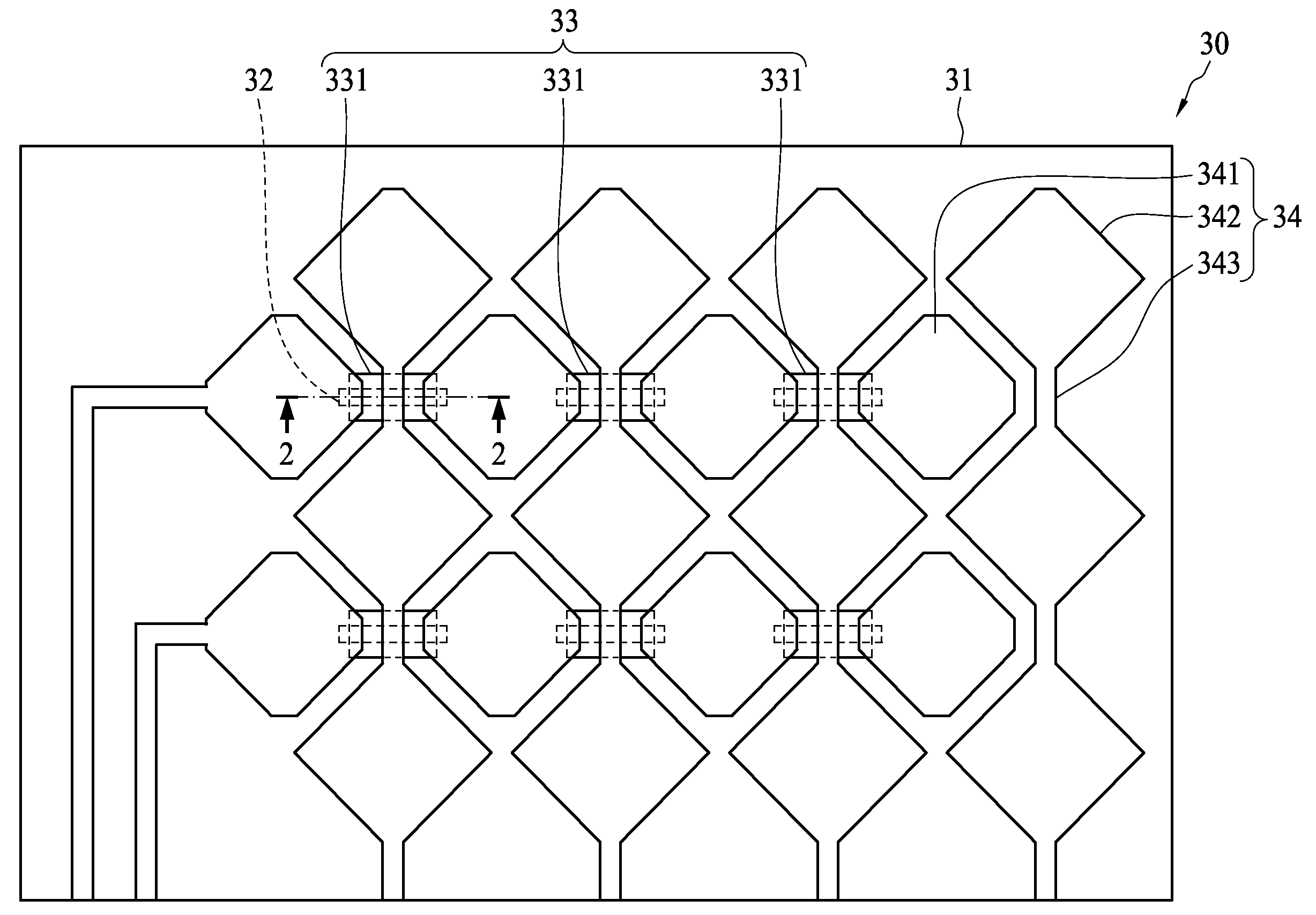
[0032]FIG. 3A is a schematic diagram of a touch panel in accordance with the present invention. As shown in FIG. 3A, a light transmission touch panel 30 comprises a transparent substrate 31, a plurality of bridging lines 32, an insulating layer 33, and a transparent conductive layer 34. The plurality of bridging lines 32 are overlaid on a surface of the transparent substrate 31. The insulating layer 33 comprises a plurality of insulating areas 331 which are respectively overlaid on the plurality of bridging lines 32. The two opposite ends of each of the bridging lines 32 are left uncovered by the patterned insulating layer 33. The transparent conductive layer 34 is overlaid on the surface of the transparent substrate 31, and comprises a plurality of first cells 341, a plurality of second cells 342 and a plurality of connecting lines 342 which are formed by a photolithography process. Furthermore, the plurality of first cells 341 and the plurality of second cells 342 are arranged in ...


PUM


Abstract

A light transmission touch panel comprises a transparent substrate, a transparent conductive layer, an insulating layer, a plurality of first metal lines, and a plurality of second metal lines. The transparent conductive layer is overlaid on a surface of the transparent substrate and comprises a plurality of first cells, a plurality of second cells and a plurality of connecting lines, wherein the plurality of first cells and the plurality of second cells are arranged in a staggered manner and the plurality of connecting lines respectively connect the adjacent second cells. The insulating layer further comprises a plurality of insulating areas, each of which is overlaid on one of the first cells. The plurality of second metal lines are respectively disposed on the connecting lines. The plurality of first metal lines are respectively disposed on the plurality of insulating areas, and respectively connect the adjacent first cells.

Description

BACKGROUND OF THE INVENTION[0001]1. Field of the Invention[0002]The present invention relates to a light transmission touch panel, and more particularly, to a touch panel having capacitance circuits.[0003]2. Description of the Related Art[0004]Touch panels have been widely applied in the fields of household appliances, communications, and electronic information devices. Common applications of the touch panel include an input interface of a personal digital assistant (PDA), an electrical appliance, a game machine, etc. The current trend of integration of touch panel and display panel allows a user to use his or her finger or a stylus to indicate a control icon shown on the panel in order to execute a desired function on a PDA, an electrical appliance, a game machine, etc. The touch panel is also applied in public information inquiry systems to provide an efficient operation system for the public.[0005]A conventional touch panel comprises a transparent substrate having a surface on wh...

Claims


Application Information

Patent Timeline
Patent Type & Authority Applications(United States)
IPC IPC(8): G06F3/041
CPCG06F2203/04111G06F3/044G06F3/0443G06F3/0446
Inventor LIANG, HSUAN HANLEE, CHIH YEN
Owner RITFAST CORP
Why Eureka
Try Eureka