Electronic apparatus and electronic camera

Active Publication Date: 2010-03-25
NIKON CORP
View PDF12 Cites 65 Cited by
  • Summary
  • Abstract
  • Description
  • Claims
  • Application Information

AI Technical Summary

Benefits of technology

[0011]An electronic apparatus according to the present invention comprises: a display at which a photographic image and a map image are displayed; and a display control unit that controls the display so as to display identifiers respectively indicating photographing locations at which a plurality of photographic images were captured over the map image displayed at the display. It is preferable that the electronic device further comprises: a storage unit in which a plurality of sets of photographic image data containing position data related to the photographing locations and map data used to display the map image are stored; and a selection unit that determines, based upon the map data, a map display range over which the map image is to be displayed at the display and selects, based upon the position data, photographing locations to be included in the map display range having been determined, and the display control unit displays the identifiers each in correspondence to one of the plurality of photographing locations selected by the selection unit.
[0012]In the electronic apparatus described above, it is preferable that the display control unit controls the display so as to display, in place of the map image currently displayed at the display, photographic images having been obtained at photographing locations corresponding to display positions at which the identifiers are displayed on the map image. Moreover, the display control unit can control the display so as to display, in place of the photographic image currently displayed at the display, the map image containing the photographic location at which the photographic image displayed at the display was photographed.
[0013]In the electronic apparatus according to the present invention, the display control unit can control the display so as to indicate a number of sets of photographic images having been captured at a given photographing location on the map image by adjusting a mode of identifier.
[0014]It is preferable that the identifiers that are displayed at the display of the electronic apparatus described above are marks correlated to photographic images. The display control unit may determine a size of each of the marks in correspondence to a number of sets of photographic image data having been obtained at a given photographing location. In this case, if a single mark displayed at a given photographing location assumes a size corresponding to a plural

Problems solved by technology

In the related art, a map image is brought up on display each time an image is captured, giving rise to an issue i

Method used


Image

  • Electronic apparatus and electronic camera
  • Electronic apparatus and electronic camera
  • Electronic apparatus and electronic camera

Examples


first embodiment

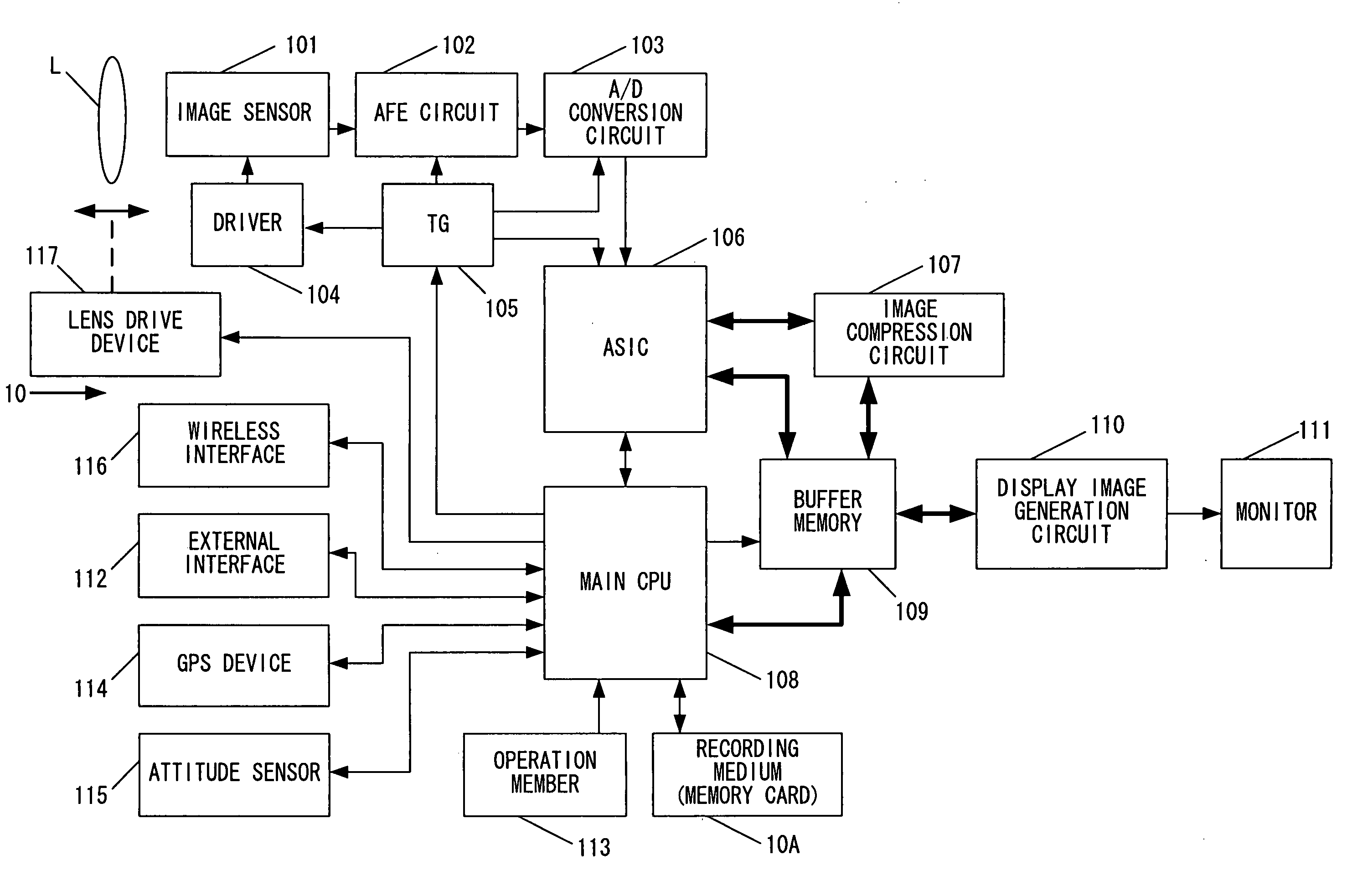
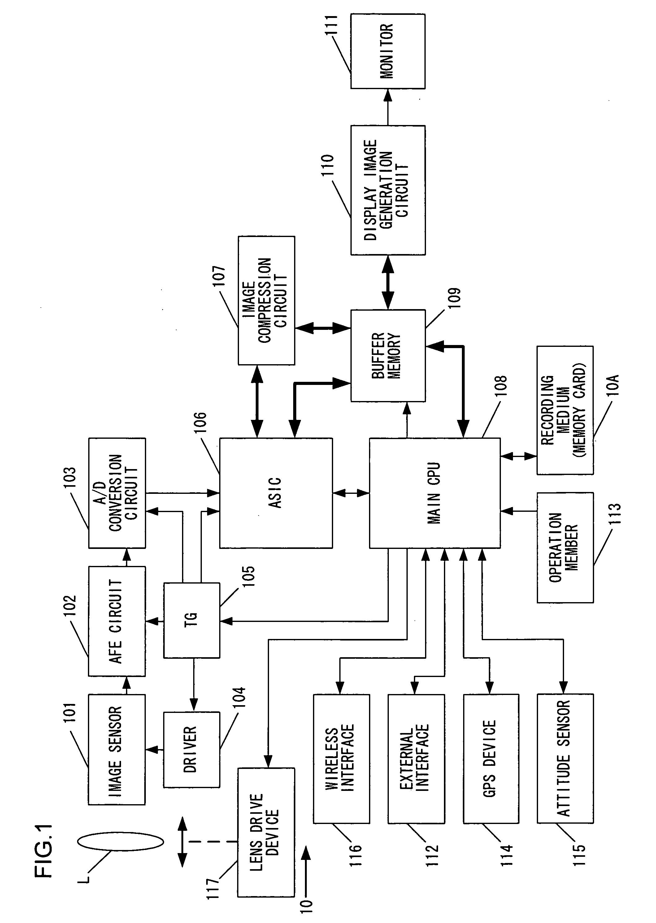
[0059]FIG. 1 is a block diagram of the essential structure adopted in an electronic camera 10 achieved in the first embodiment of the present invention. A timing generator (TG) 105 in FIG. 1 provides timing signals to a driver 104, an AFE (analog front end) circuit 102, an A / D conversion circuit 103 and an image processing circuit 106 in response to an instruction output from a main CPU 108. The driver 104 provides a drive signal for an image sensor 101.

[0060]A photographic lens L forms a subject image on an imaging surface of the image sensor 101. The image sensor 101, which may be constituted with a CCD image sensor or the like equipped with a plurality of photoelectric conversion elements each corresponding to a pixel, captures the subject image formed on the imaging surface and outputs photoelectric conversion signals corresponding to the brightness of the subject image. R (red), G (green) and B (blue) color filters are disposed at the imaging surface of the image sensor 101 so ...

second embodiment

[0156]The second embodiment of the present invention is now described. The following explanation focuses on the difference from the first embodiment, with the same reference numerals assigned to components identical to those in the first embodiment, to preclude the necessity for a repeated explanation. In other words, unless a given component is particularly noted, it is identical to the corresponding component in the first embodiment. The second embodiment enables adjustment of the display magnification factor at which the reproduced image is displayed.

[0157]FIG. 7 presents an example of an image that may be brought up on display at the liquid crystal monitor 111 through the processing executed in step S19 (see FIG. 5). The main CPU 108 may switch the display contents as described below. Namely, as the switch 113d is operated while the full-screen display of a reproduced image is up at the liquid crystal monitor 111, the main CPU 108 switches from the full screen display in FIG. 7 ...

third embodiment

[0166]The third embodiment of the present invention is now described. The following explanation focuses on the difference from the first and second embodiments, with the same reference numerals assigned to components identical to those in the first and second embodiments, to preclude the necessity for a repeated explanation. In other words, unless a given component is particularly noted, it is identical to the corresponding component in the first and second embodiments. In reference to the third embodiment, the concepts of variations 2, 3 and 4 are described in further detail.

[0167]FIG. 11 presents an example of a setting menu screen that may be brought up on display at the liquid crystal monitor 11 by the main CPU 108 in response to an operation of the menu switch 113c. In response to a rotation operation signal output from the dial 113f, the main CPU 108 switches the selected option and as the OK switch 113g is operated, the main CPU displays at the liquid crystal monitor 111 a me...


PUM


Abstract

An electronic apparatus includes: a display at which a photographic image and a map image are displayed; and a display control unit that controls the display so as to display identifiers respectively indicating photographing locations at which a plurality of photographic images were captured over the map image displayed at the display.

Description

[0001]This application is a continuation of International Application No. PCT / JP2007 / 069498 filed Oct. 4, 2007.INCORPORATION BY REFERENCE[0002]The disclosures of the following applications are herein incorporated by reference:[0003]Japanese Patent Application No. 2006-273038 filed Oct. 4, 2006[0004]Japanese Patent Application No. 2007-124289 filed May 9, 2007[0005]International Application No. PCT / JP2007 / 069498 filed Oct. 4, 2007.BACKGROUND OF THE INVENTION[0006]1. Field of the Invention[0007]The present invention relates to an electronic apparatus and electronic camera that enable display of a photographing location on a map image.[0008]2. Description of Related Art[0009]Japanese Laid-open Patent Publication No. 2006-148514 discloses a camera that executes photographing position measurement based upon a signal received from a GPS satellite. At the camera in the related art, the photographing location and the subject position are indicated on a map image. The map display range is au...

Claims


Application Information

Patent Timeline
IPC IPC(8): H04N5/225H04N5/222G08B21/00
CPCG06T17/05H04N5/765H04N9/8205H04N5/775H04N5/85H04N5/772
Inventor SOGOH, CHIEOHMURA, AKIRA
Owner NIKON CORP
Why Eureka
Try Eureka