Inner-Rotor-Type Heat Dissipating Fan

a heat dissipating fan and inner-rotor technology, applied in the direction of positive displacement liquid engines, piston pumps, liquid fuel engines, etc., can solve the problems of increasing the need for heat dissipation with high efficiency, reducing the efficiency of heat dissipation, and generally less stable rotation of outer-rotor-type motors. achieve the effect of preventing magnetic flux leakage and electromagnetic interferen

Active Publication Date: 2010-03-25
SUNONWEALTH ELECTRIC MACHINE IND
View PDF15 Cites 15 Cited by
  • Summary
  • Abstract
  • Description
  • Claims
  • Application Information

AI Technical Summary

Benefits of technology

[0010]It is therefore the primary objective of this invention to provide an inner-rotor-type heat dissipating fan that overcomes the problems of the prior art described above to prevent magnetic flux leakage and electromagnetic interference.
[0011]An inner-rotor-type heat dissipating fan according to the preferred teachings of the present invention includes a fan housing, a seal casing, an inner-rotor-type motor, an impeller and a circuit board. The fan housing includes an outer frame portion having an air inlet and an air outlet respectively in two ends thereof, and a motor casing coupling to the outer frame portion through a plurality of connecting members. A passageway connects to and between the air inlet and the air outlet. The seal casing is a hollow housing made of magnetically conductive material. One end of the seal casing forms a connecting portion coupling to the motor casing. The inner-rotor-type motor is mounted inside the seal casing and includes a rotor and a stator. The rotor is rotatably received in the stator and has a shaft and a magnetic element fixed to an outer periphery of the shaft and facing the stator. The impeller is coupled to the shaft and outside the seal casing. The circuit board is electrically connected to the stator. By this configuration, rotation stability of the impeller is enhanced by the inner-rotor-type motor, airflow generated by rotation of the impeller is effectively concentrated and guided by the fan housing and a sealing effect for avoiding magnetic flux leakage and electromagnetic interference is provided by the seal casing. Accordingly, heat dissipating efficiency is enhanced.
[0014]In an example, the motor casing is a sleeve having a positioning portion formed on an inner periphery thereof and a positioning member and an end cap are mounted in the motor casing, with two axial sides of the positioning member respectively abutting against the positioning portion and engaging with the end cap, with the circuit board being disposed between the positioning member and the end cap, with the circuit board being spaced from the stator by the positioning member. Accordingly, heat dissipating effect of the circuit board is prevented from being adversely affected by the large amount of heat resulting from operation of the stator to avoid damage to the associated electronic elements.
[0015]In an example, the motor casing is a sleeve having a supporting portion formed on an inner periphery thereof, with the connecting portion of the seal casing abutting against the supporting portion. Accordingly, combination of the seal casing and the motor casing is improved.
[0016]In an example, the connecting portion of the seal casing includes an outwardly-expanding section while an annular shoulder forms on an outer periphery of the seal casing and adjacent to the outwardly-expanding section, with a positioning portion being formed on an inner periphery of the motor casing of the fan housing, with the annular shoulder and the positioning portion abutting against and combining with each other. Accordingly, combination of the seal casing and the motor casing is improved.

Problems solved by technology

However, in comparison with inner-rotor-type motors, outer-rotor-type motors are generally less stable in rotation and can only provide a lower rotation rate at full speed.
However, owing to the current trend of research and development in electronic products, which includes high operation speed, function integrity, and miniaturization, heat dissipation with high efficiency has become an urgent demand.
Unfortunately, the conventional heat dissipating fans with outer-rotor-type motors can not fulfill the heat dissipation need of these electronic products.
However, when it is desired to dissipate heat in various electronic products with the heat dissipating fan 80, airflow generated by rotation of the impeller 85 can not be effectively guided to a heat-generating portion in an electronic product since a fan frame is absent from the heat dissipating fan 80.
Thus, heat dissipating efficiency of the heat dissipating fan 80 is low.

Method used


Image

  • Inner-Rotor-Type Heat Dissipating Fan
  • Inner-Rotor-Type Heat Dissipating Fan
  • Inner-Rotor-Type Heat Dissipating Fan

Examples


Embodiment Construction

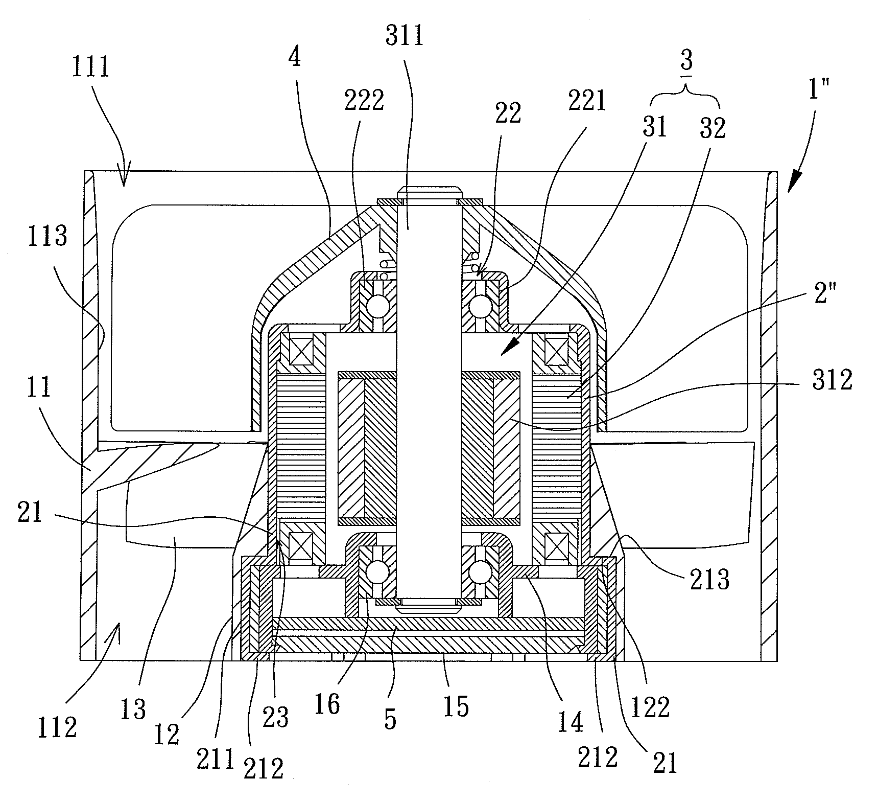
[0031]An inner-rotor-type heat dissipating fan of a first embodiment according to the preferred teachings of the present invention is shown in FIGS. 4 and 5 of the drawings. According to the first embodiment form shown, the inner-rotor-type heat dissipating fan includes a fan housing 1 made of plastic material and formed by injection molding, a seal casing 2 mounted inside the fan housing 1, an inner-rotor-type motor 3 mounted inside the seal casing 2, an impeller 4 coupled to the inner-rotor-type motor 3 and a circuit board 5 electrically connected to the inner-rotor-type motor 3 to control the inner-rotor-type motor 3 for driving the impeller 4 to rotate. Thus, airflow generated by rotation of the impeller 4 is concentrated and guided by the fan housing 1, and the seal casing 2 provides a sealing effect for avoiding magnetic flux leakage and electromagnetic interference.

[0032]According to the preferred form shown, the fan housing 1 includes an outer frame portion 11 having an air ...


PUM


Abstract

An inner-rotor-type heat dissipating fan comprises a fan housing, a seal casing, an inner-rotor-type motor, an impeller and a circuit board. The fan housing includes an outer frame portion and a motor casing. The seal casing is a hollow housing made of magnetically conductive material. One end of the seal casing forms a connecting portion coupling to the motor casing. The inner-rotor-type motor is mounted inside the seal casing. The impeller is coupled to the inner-rotor-type motor and outside the seal casing. The circuit board is electrically connected to the stator. By this configuration, rotation stability of the impeller is enhanced by the inner-rotor-type motor, airflow generated by rotation of the impeller is effectively concentrated and guided by the fan housing and a sealing effect for avoiding magnetic flux leakage is provided by the seal casing. Consequently, heat dissipating efficiency is enhanced.

Description

BACKGROUND OF THE INVENTION[0001]1. Field of the Invention[0002]The present invention relates to a heat dissipating fan and, more particularly, to a heat dissipating fan including a motor having an inner rotor.[0003]2. Description of the Related Art[0004]Referring to FIG. 1, a conventional heat dissipating fan 70 including an outer-rotor-type motor is shown. Specifically, the heat dissipating fan 70 includes a frame 71 with a shaft tube 711 disposed inside the frame 71 and receiving a bearing 712, a stator 72 mounted around the shaft tube 711, a circuit board 73 mounted around the shaft tube 711 and electrically connecting with the stator 72, and a rotor 74 having a shaft 741 and an impeller 742. One end of the shaft 741 rotatably extends through the bearing 712, and the impeller 742 is mounted to the other end of the shaft 741. The impeller 742 includes a permanent magnet 743 facing the stator 72. The circuit board 73 controls the stator 72 to generate an alternating magnetic field...

Claims


Application Information

Patent Timeline
Patent Type & Authority Applications(United States)
IPC IPC(8): H05K7/20
CPCF04D29/526F04D29/601F04D25/0606H02K9/06H02K7/14F04D29/646
Inventor HORNG, ALEXYIN, TSO-KUO
Owner SUNONWEALTH ELECTRIC MACHINE IND
Why Eureka
Try Eureka