
Golf ball with improved flight performance

a golf ball and flight performance technology, applied in the field of solid construction golf balls, can solve the problems of asymmetric flight performance, difficult to identify incremental performance improvement using these methods, and difference in pressure, and achieve the effect of improving flight performan

Active Publication Date: 2010-03-25
ACUSHNET CO
View PDF28 Cites 16 Cited by
  • Summary
  • Abstract
  • Description
  • Claims
  • Application Information

AI Technical Summary

Benefits of technology

The present invention is about a golf ball with a layer of liquid inside to improve its flight performance. This liquid layer helps to decrease the spin of the ball during the initial stages of flight, which makes it easier for the ball to travel in a straight line. The invention also includes a multi-layer construction that separates the solid core of the ball from the outer layers, which further enhances the ball's ability to spin and decay during flight. Additionally, a solid construction golf ball has been developed that includes a solid core, a cover layer, and an intermediate layer that contains a porous support and a viscous liquid movable within it. This new design helps to achieve even better flight performance.

Problems solved by technology

The flight of a golf ball is determined by many factors, however, the majority of the properties that determine flight are outside of the control of a golfer.
Flight consistency is a significant problem for manufacturers because many golf ball dimple patterns and / or dimple shapes that yield increased flight distances also result in asymmetric flight performance.
Furthermore, it is difficult to identify incremental performance improvements using these methods due to the statistical noise generated by environmental conditions, which necessitates large sample sizes for sufficient confidence intervals.
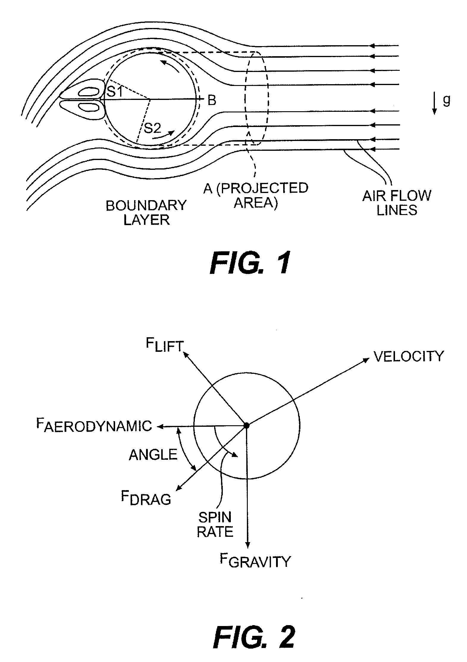
It results from a difference in pressure that is created by a distortion in the air flow that results from the back spin of the ball.
The difference between the high pressure in front of the ball and the low pressure behind the ball reduces the ball speed and acts as the primary source of drag for a golf ball.
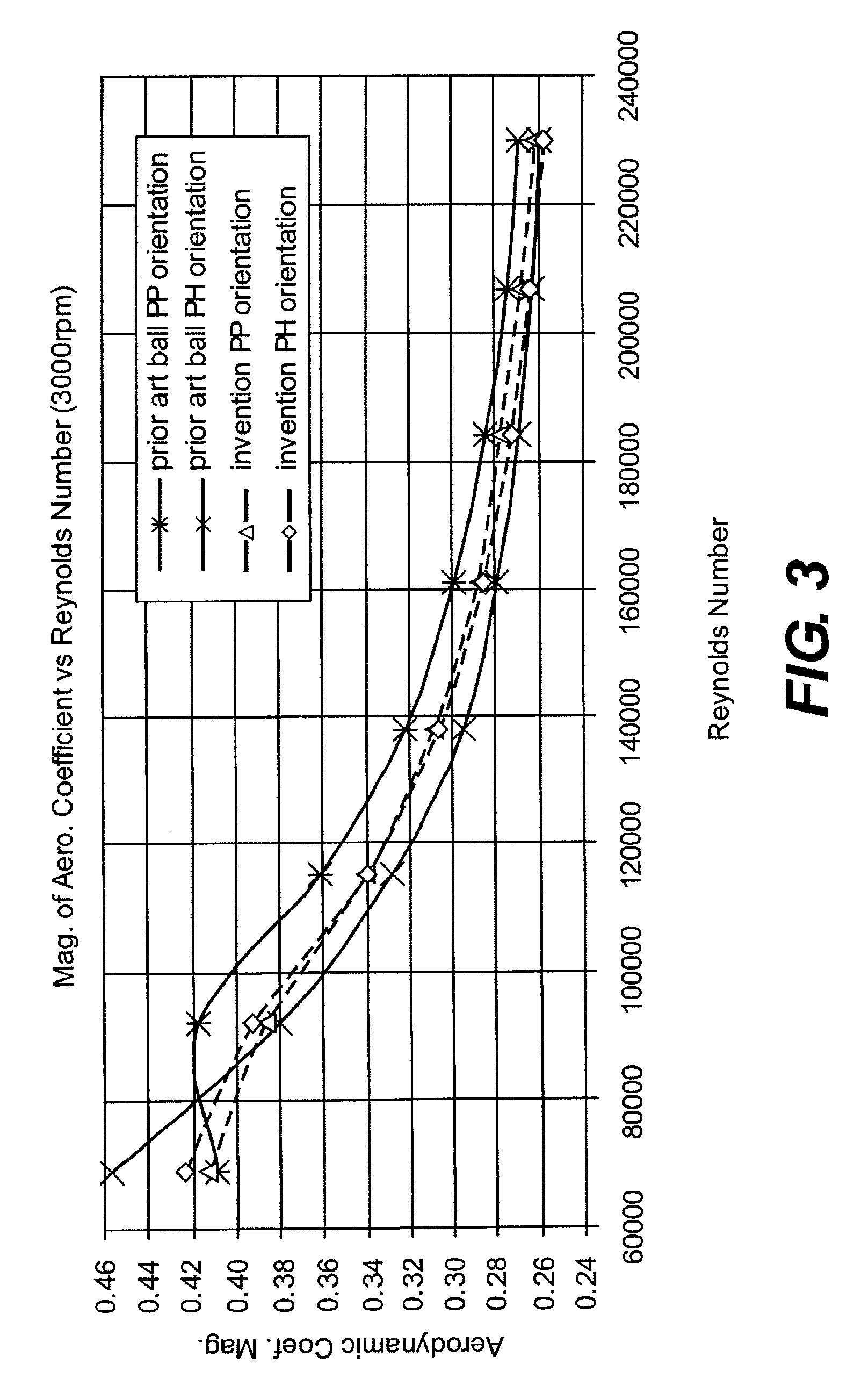
It has now been discovered, contrary to the disclosures of these patents, that reduced high-speed drag and increased low speed lift does not necessarily result in improved flight performance.
For example, excessive high-speed lift or excessive low-speed drag may result in undesirable flight performance characteristics.

Method used


Image

  • Golf ball with improved flight performance
  • Golf ball with improved flight performance
  • Golf ball with improved flight performance

Examples


third embodiment

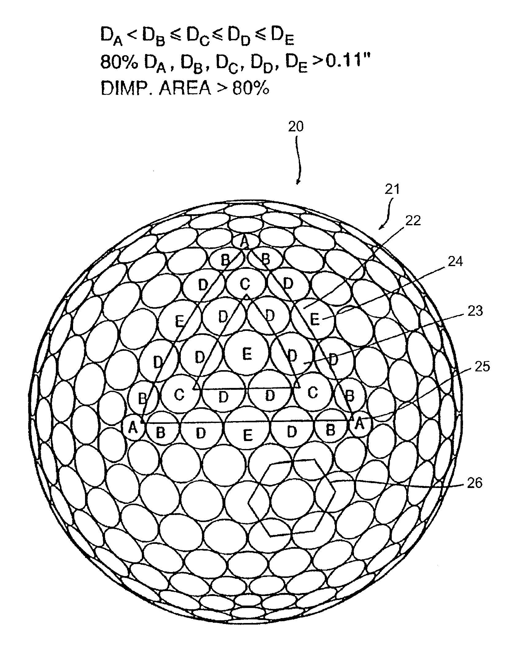
[0094]One embodiment of the present invention contemplates dimple coverage of greater than about 80 percent. For example, the percentages of surface area covered by dimples in the embodiments shown in FIGS. 7-8 and 9-12 are about 85.7 percent and 82 percent, respectively whereas the ball shown in FIG. 5 has less than 80 percent of its surface covered by dimples. The percentage of surface area covered by dimples in the third embodiment shown in FIGS. 13-14 is also about 82 percent, whereas prior art octahedral balls have less than 77 percent of their surface covered by dimples, and most have less than 60 percent. Thus, there is a significant increase in surface area contemplated for the golf balls of the present invention as compared to prior art golf balls.

Parting Line

[0095]A parting line, or annular region, about the equator of a golf ball has been found to separate the flow profile of the air into two distinct halves while the golf ball is in flight and reduce the aerodynamic forc...

first embodiment

[0098]In another embodiment, there are more than two parting lines that do not intersect any dimples. For example, the octahedral golf ball shown in FIGS. 13-14 contains three parting lines 38 that do not intersect any dimples. This decreases the percentage of the outer surface as compared to the first embodiment, but increases the symmetry of the dimple pattern.

[0099]In another embodiment, the golf balls according to the present invention may have the dimples arranged so that there are less than four parting lines that do not intersect any dimples.

Dimple Count

[0100]In one embodiment, the golf balls according to the present invention have about 300 to about 500 total dimples. In another embodiment, the dimple patterns are icosahedron patterns with about 350 to about 450 total dimples. For example, the golf ball of FIGS. 7-8 have 362 dimples. In the golf ball shown in FIGS. 9-12, there are 392 dimples and in the golf ball shown in FIGS. 13-14, there are 440 dimples.

Dimple Diameter

[01...


PUM


Abstract

A golf ball with aerodynamic coefficient magnitude and aerodynamic force angle, resulting in improved flight performance, such as increased carry and flight consistency regardless of ball orientation. In particular, the present invention is directed to a golf ball having increased flight distance as defined by a set of aerodynamic requirements, at particular spin ratios and Reynolds Numbers. The invention is also directed toward golf balls having high spin decay rates during the first second of flight that yields improved flight performance and longer ball flight

Description

FIELD OF THE INVENTION[0001]The present invention relates to a solid construction golf ball having high spin decay during the first second of flight that yields improved flight performance and longer ball flight.BACKGROUND OF THE INVENTION[0002]The flight of a golf ball is determined by many factors, however, the majority of the properties that determine flight are outside of the control of a golfer. While a golfer can control the speed, the launch angle, and the spin rate of a golf ball by hitting the ball with a particular club, the final resting point of the ball depends upon golf ball construction and materials, as well as environmental conditions, e.g., terrain and weather. Since flight distance and consistency are critical factors in reducing golf scores, manufacturers continually strive to make even the slightest incremental improvements in golf ball flight consistency and flight distance, e.g., one or more yards, through various aerodynamic properties and golf ball construct...

Claims


Application Information

Patent Timeline
Patent Type & Authority Applications(United States)
IPC IPC(8): A63B37/02A63B37/12
CPCA63B37/0039A63B37/0047A63B37/0066A63B2037/085A63B37/0096A63B37/0006A63B37/0091A63B37/0019A63B37/002A63B37/0075A63B37/0089A63B37/009A63B37/0016A63B37/00065
Inventor NARDACCI, NICHOLAS M.BISSONNETTE, LAURENT
Owner ACUSHNET CO
Learn More