
Endoscope for oblique viewing

a technology of endoscope and oblique viewing, which is applied in the field of endoscope for oblique viewing, can solve the problems of difficult optical filter disposal, inability to directly apply to the oblique-viewing endoscope objective system, and increased distal end portion size, so as to achieve the effect of reducing insertability and operability

Active Publication Date: 2010-03-25
OLYMPUS CORP
View PDF5 Cites 134 Cited by
  • Summary
  • Abstract
  • Description
  • Claims
  • Application Information

AI Technical Summary

Problems solved by technology

In the oblique-viewing objective system 102, however, it is difficult to dispose an optical filter because a space for disposition of a visual field direction converting element is lost if an optical filter is disposed in the objective system.
Also, the configuration of the conventional straight-viewing objective system 202 having optical filters is not an optimum lens configuration for an oblique-viewing endoscope and, therefore, cannot be directly applied to the oblique-viewing endoscope objective system 102.
However, the size of the distal end portion is thereby increased to produce adverse effects in terms of insertability and operability.
However, if the diameter of the objective system is reduced, the desired strength of the lens unit frame cannot be secured.
In the oblique-viewing endoscope, however, the entire length of the image pickup system including the objective system-image pickup device structure is long and, therefore, it is not easy to reduce the diameter of the distal end portion 5.
An objective system having a reduced entire length is lower in optical performance and is incapable of securing a space for disposition of optical filters for color tone and image quality corrections, because the number of constituent lenses is small.
Therefore, it is not easy to suitably design such an objective system in terms of optical performance with an image pickup device smaller in size and having an increased number of pixels.
If separation occurs, moisture enters from the outside along the separated portions to cause dew condensation of water vapor on a lens inner surface and, hence, a fog on the lens inner surface such that an image to be observed is difficult to see.
Reducing variations in performance of the objective system requires improving the accuracy of working on optical components including the lenses and the lens frame F, but mass production of high-accuracy component parts is not easy to perform.
Also, it is difficult to perform the assembly process if no gap for adjustment is provided.
The first lens L1, which is a negative lens, is higher in refractive power than other lenses and is difficult to adjust finely.
Also, there is a possibility of considerable degradation in some other optical performance as a result of eccentricity adjustment to the first lens L1.
Conversely, if an adjustment is made to prevent a partial defocus, variation in the visual field direction becomes so large that the possibility of variation in the field of view and the possibility of occurrence of an image cut-off are increased.
Also, if the size of the first lens L1 in the objective system is increased, the distance between the objective system and the illumination system becomes so large that it is difficult for the illumination system to lightly and uniformly illuminate even a peripheral portion of the field of view for observation.
At the time of closeup observation in particular, the illumination system cannot sufficiently illuminate in the field of view for observation; a peripheral portion of the field is left dark.
Further, in a case where the field of view for observation is made wider, that is, the field of view in the objective system is increased, for the purpose of improving observability, it is more difficult for the illumination system to sufficiently illuminate in the field of view and there is a possibility of a peripheral portion of the field of view for observation being dark.
On the other hand, in the case of a disposition enabling suitable luminous intensity distribution at the time of closeup observation, it is difficult to suitably illuminate a lower portion of the view.
This is difficult to achieve because of the structure of the lens unit frame.

Method used


Image

  • Endoscope for oblique viewing
  • Endoscope for oblique viewing
  • Endoscope for oblique viewing

Examples


embodiment 1

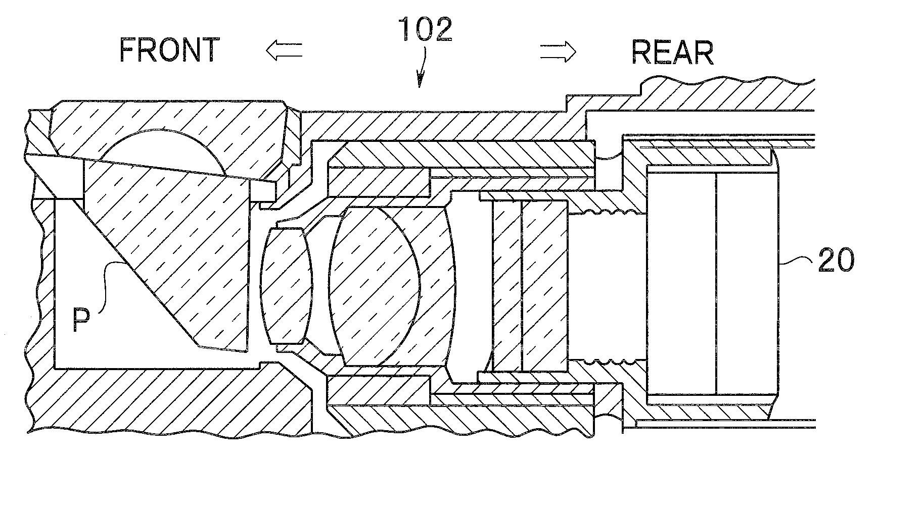
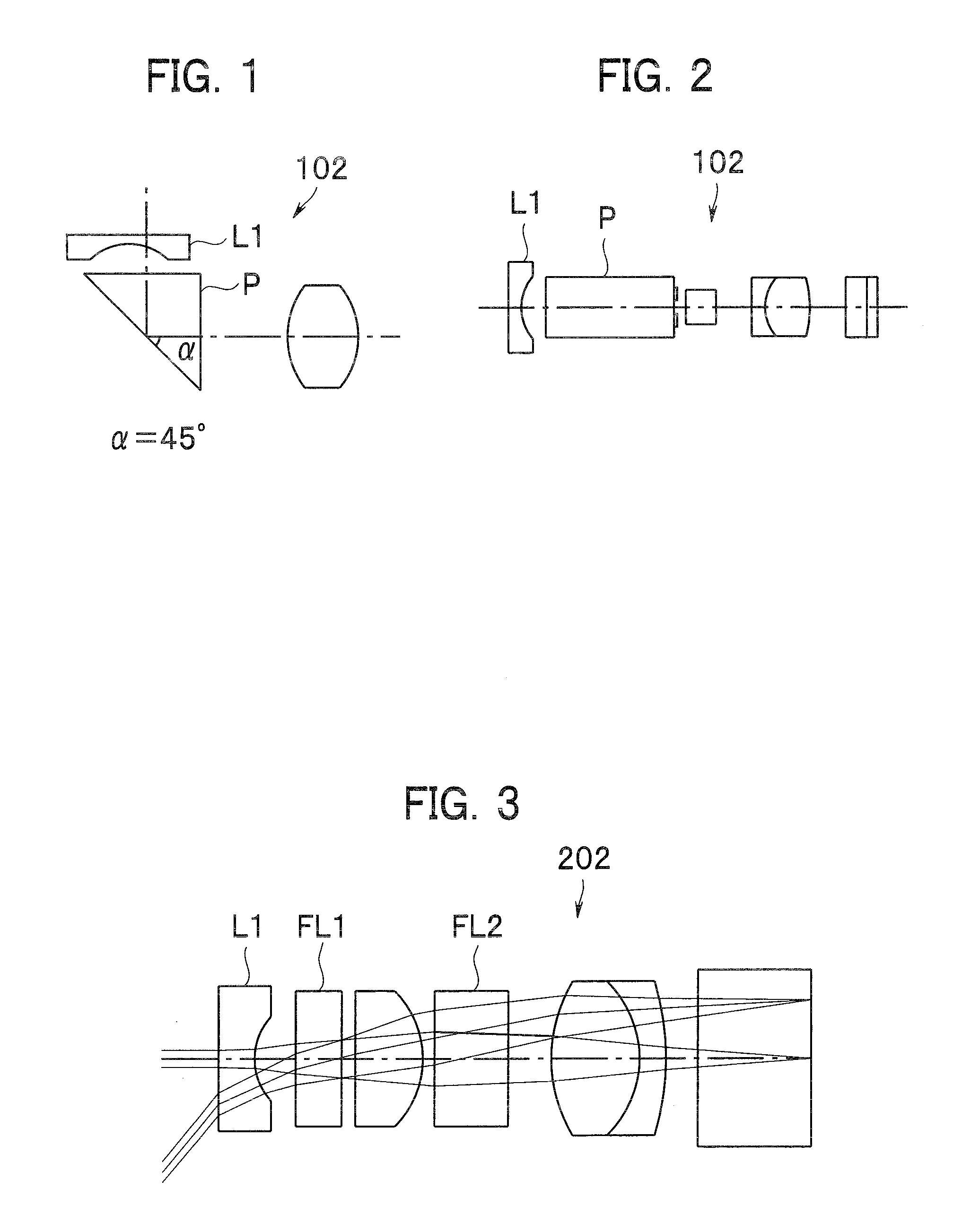
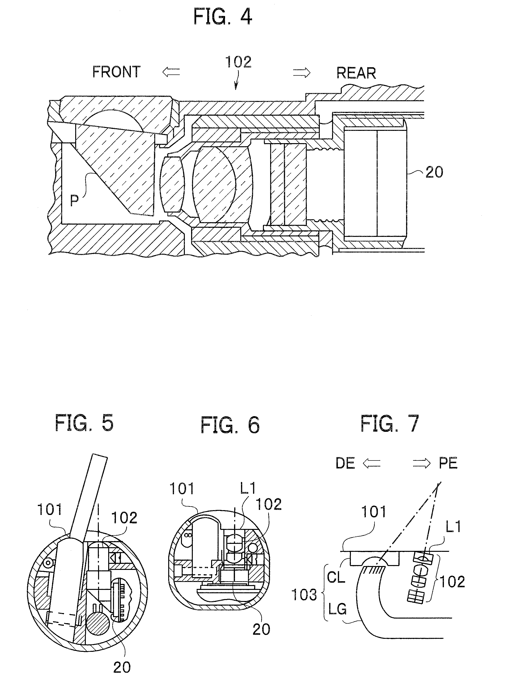
[0144]As shown in FIG. 11, an objective system 2A of an oblique-viewing endoscope 1A in Embodiment 1 has a positive front lens group G1, a positive rear lens group G2, a prism P interposed between the front and rear lens groups as a visual field direction converting element, and a stop S provided between the front lens group G1 and the prism P. In FIG. 11 and other sectional views each taken along the optical axis of an objective system and showing the configuration of the objective system, reference character r denotes a curved surface of a component reference character d denotes the distance between surfaces on the optical axis (the thickness of each optical member and the air distance); and the optical axis Z1 is shown in straight line form.

[0145]That is, in the objective system 2A, the front lens group G1 constituted by a first lens L1 having a negative refractive power and a second lens L2 having a positive refractive power is disposed in front of the prism P (at the left side ...

embodiment 2

[0152]FIG. 21 shows the configuration of an objective system 2B of an oblique-viewing endoscope 1B in Embodiment 2. The configuration of the objective system 2B in the present embodiment is similar to that of the objective system 2A in Embodiment 1. The same reference characters are used for the same components as those in Embodiment 1, and the description for the same components will not be repeated. In the objective system 2B in the present embodiment, a high-refraction material having a refractive index of about 2.1 or more is used as the material of a prism PB which is a visual field direction converting element. Because of the use of the high-refraction material, the air-converted length of the prism PB is short and the substantial space for disposition of the prism PB is small. FIGS. 22A to 22D are aberration diagrams of the objective system 2B in the present embodiment.

[0153]Numeric data on Embodiment 2 is shown below.

Surface No.rdn(e)ν(e)1∞0.37161.8881440.5320.70250.53261.3∞...

embodiment 3

[0154]FIG. 23 shows the optical configuration of an objective system 2C of an oblique-viewing endoscope 1C in Embodiment 3. The configuration in the present embodiment is similar to that of the objective system 2A in Embodiment 1. The same reference characters are used for the same components as those in Embodiment 1, and the description for the same components will not be repeated. In the present embodiment, a first lens L1C is formed of a sapphire crystal material. The refractive index of sapphire is rather low but use of sapphire is advantageous in that the hardness of sapphire is high and the lens outer surface is resistant to scratch or the like. In an endoscope using a lens having a small outside diameter of several millimeters in particular, even a small scratch may badly influence the image quality by causing image nonuniformity or a flare for example. In the oblique-viewing endoscope 1C using the high-hardness material, however, such band influence cannot occur easily. FIGS...


PUM


Abstract

An endoscope for oblique viewing including an image pickup device, a front lens group having a positive refractive power, a prism disposed on the CCD side of the front lens group, and a rear lens group disposed on the CCD side of the prism and having a positive refractive power.

Description

[0001]This application claims benefit of Japanese Application No. 2008-240676 filed in Japan on Sep. 19, 2008, the contents of which are incorporated by this reference.BACKGROUND OF THE INVENTION[0002]1. Field of the Invention[0003]The present invention relates to an endoscope for oblique viewing and, more particularly, to an endoscope for oblique viewing having a visual field direction converting element.[0004]2. Description of the Related Art[0005]Endoscopes include endoscopes for oblique viewing having a visual field direction different from the endoscope longitudinal direction (also referred to as “oblique-viewing endoscope” below, “endoscope” in single form denoting an oblique-viewing endoscope). Oblique-viewing endoscopes include a side-viewing endoscope having a visual field direction perpendicular to the endoscope longitudinal direction, a forward-oblique-viewing endoscope having a visual field direction inclined toward a distal end, and rearward-oblique-viewing endoscope ha...

Claims


Application Information

Patent Timeline
Patent Type & Authority Applications(United States)
IPC IPC(8): A61B1/06
CPCA61B1/00177A61B1/00179A61B1/00183G02B23/2476G02B7/023G02B23/243A61B1/05
Inventor TAKASUGI, YOSHIHARUAKIYAMA, DAISUKE
Owner OLYMPUS CORP
Features
  • Generate Ideas
  • Intellectual Property
  • Life Sciences
  • Materials
  • Tech Scout
  • Unparalleled Data Quality
  • Higher Quality Content
  • 60% Fewer Hallucinations
Learn More