Kit Containing Combination Absorbable Staple and Non-absorbable Suture, And Method Of Using Same

Inactive Publication Date: 2010-03-25
ILAHI OMER A
View PDF16 Cites 10 Cited by
  • Summary
  • Abstract
  • Description
  • Claims
  • Application Information

AI Technical Summary

Problems solved by technology

Minimally invasive approaches do not allow for easily creating drill holes and passing sutures through them, and so the use of fixation devices has increased, as a direct result of the increasing popularity of minimally invasive musculoskeletal procedures, such as arthroscopic surgery.
Such interference screws cannot be used to secure soft tissue to a bone trough, however.
In that case, drilling out the other side to create a small passage through which a traction suture may be passed risks injuring the structures on the other side of the bone.
Problems with this device include suture breakage as the screw driver is turned many times during screw advancement, damage to the soft tissue by the advancing screw, and wrapping of the soft tissue around the screw as it is being advanced, leading to changing position of the soft tissue in the bone tunnel.
Additionally, the presence of a large screw-type device can be problematic, even if made of absorbable material.
Large absorbable devices often don't get fully reabsorbed, leading to the formation of localized foreign body reactions that can weaken bones, resulting in fracture, or affect future surgical intervention should the need arise.
On the other hand, metal screws can become dislodged over time and lead to irritation of surrounding soft tissues.
But suture management can be an issue and tangled suture can complicate the procedure.
Absorbable tacks have had a poor record of maintaining fixation of soft tissue to bone long enough to allow firm healing to occur.
There is a natural weak point where the broad head of a tack meets the narrow shaft, and consequently failure at this juncture often occurs, compromising surgical results.
Removing metal staples can be problematic; and imaging the adjacent area with subsequent magnetic resonance imaging or computed tomography is compromised by the metal of the staple.
Unfortunately, a common problem with large bioabsorbable stapes and tacks is a large mass of indefinitely partially degraded absorbable material.

Method used


Image

  • Kit Containing Combination Absorbable Staple and Non-absorbable Suture, And Method Of Using Same
  • Kit Containing Combination Absorbable Staple and Non-absorbable Suture, And Method Of Using Same
  • Kit Containing Combination Absorbable Staple and Non-absorbable Suture, And Method Of Using Same

Examples


Embodiment Construction

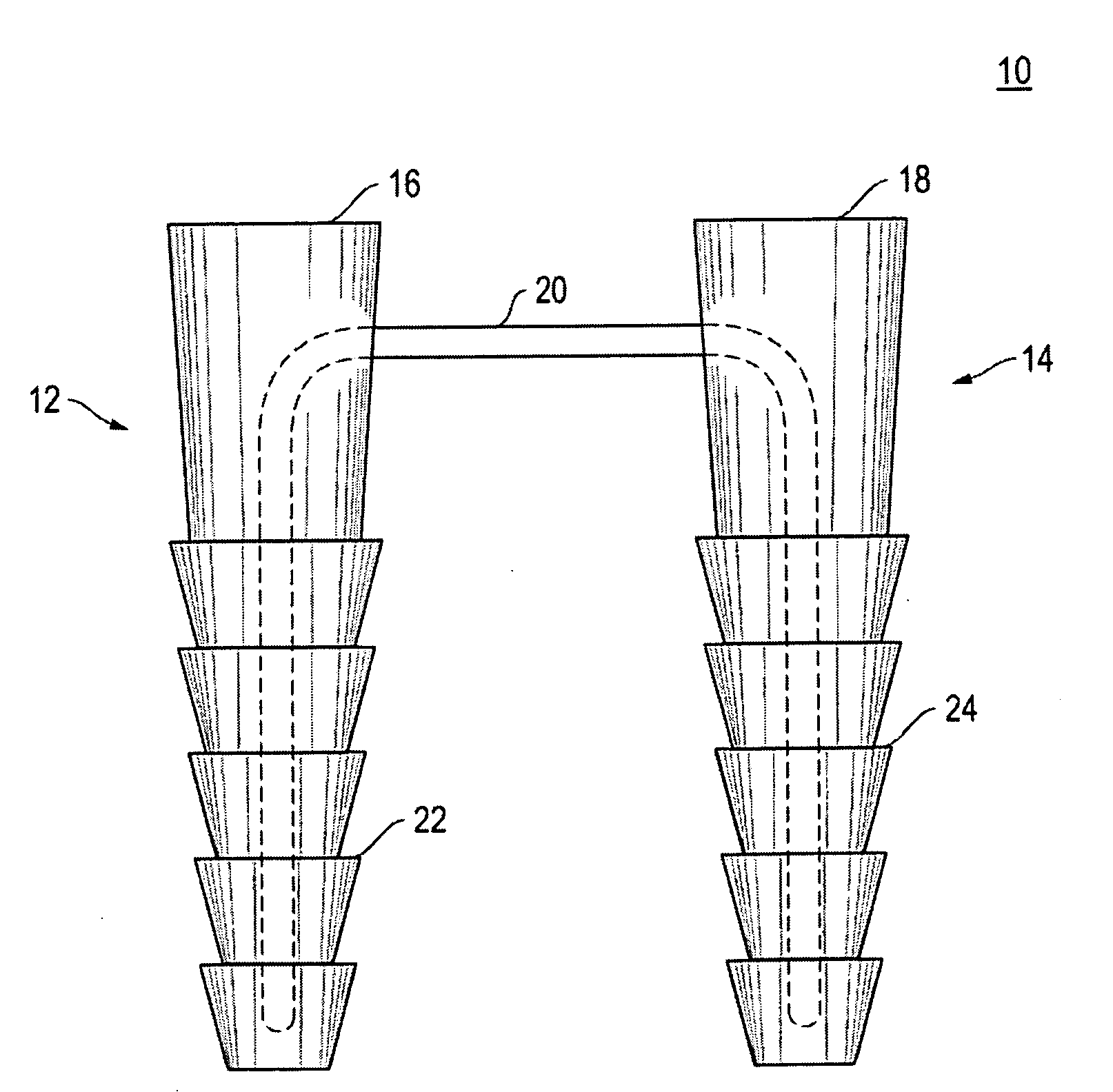
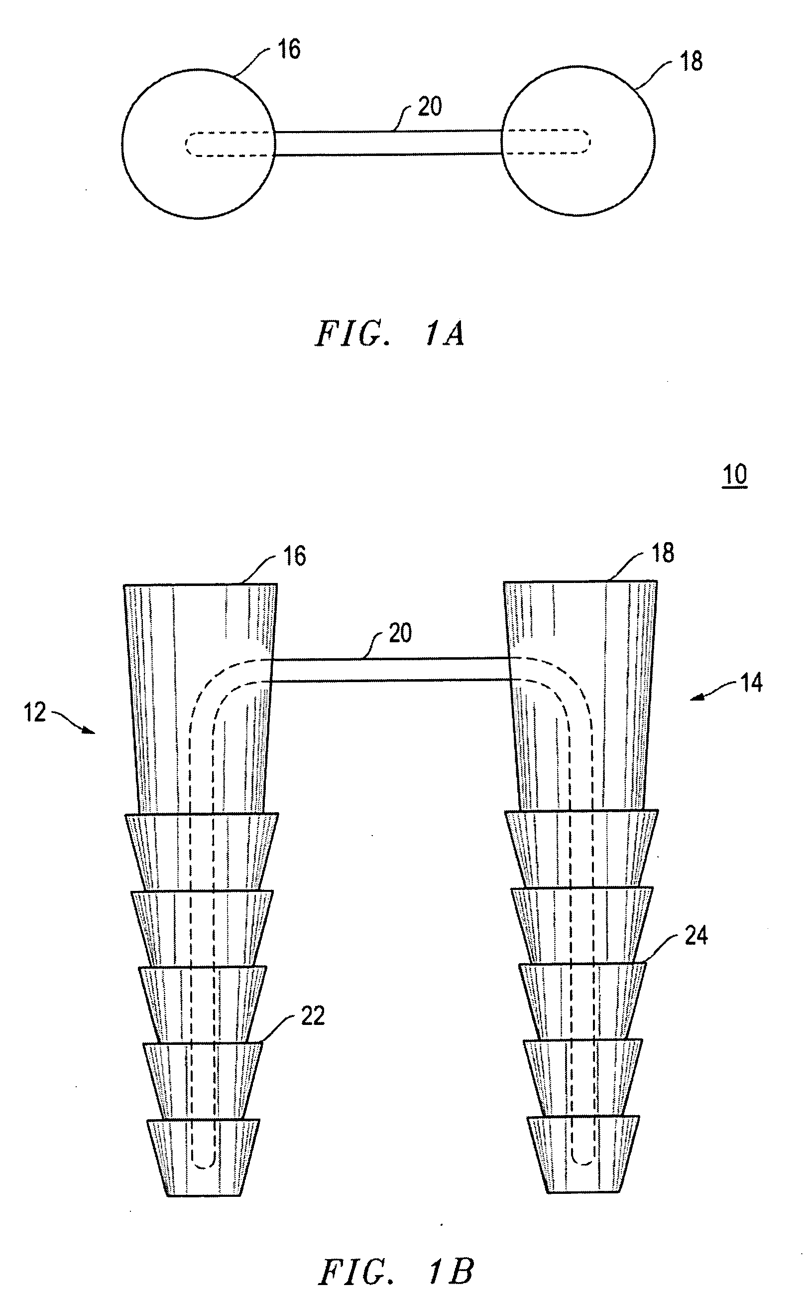
[0048]In FIG. 1, the suture-staple 10 of the present invention is shown. The suture-staple 10 includes two spikes 12, 14 with their bases 16, 18 connected with a suture 20. The suture 20 is firmly embedded in each spike 12, 14, and connects the bases 16, 18. The two spikes 12, 14 are separated by a span ranging from four millimeters to sixteen millimeters. The diameter of each base 16, 18 is the same, ranging from two millimeters to five millimeters. The total length of each spike 12, 14 is the same, ranging from four millimeters to twenty millimeters.

[0049]In the preferred embodiment, the suture 20 is a size number 2, non-absorbable, and braided, but could also be absorbable or non-braided, and can range in size from number zero to number five. The soft tissue can be a ligament, a tendon, or any other soft connective tissue. In the preferred embodiment the spikes 12, 14 have barbs 22, 24, but may also have smooth or rough walls. The spikes 12, 14 are made of absorbable material, bu...


PUM


Abstract

A soft tissue attachment kit, for attaching a patient's soft tissue to a patient's bone at a soft tissue attachment site that is underneath muscle and fat, includes:a. a collection of suture-staples of various sizes, each suture-staple including:i. two spikes, each spike having a base; andii. a suture embedded in each spike, and connecting the bases of the two spikes;b. a collection of double-barrel insertion cannulas for:i. receiving one of the suture-staples; andii. allowing the suture-staple to pass through;c. a collection of double-barrel impactors, for tapping the suture-staple into the patient's bone; andd. a collection of insertion sheaths, each insertion sheath adapted fori. penetrating the patient's fat and muscle overlying the soft tissue attachment site;ii. receiving the double-barrel insertion cannula; andiii. allowing the double-barrel insertion cannula to pass through the insertion sheath to contact the patient's bone.

Description

CROSS-REFERENCES TO RELATED APPLICATIONS[0001]None.STATEMENT REGARDING FEDERALLY SPONSORED RESEARCH OR DEVELOPMENT[0002]None.REFERENCE TO A “SEQUENCE LISTING,” A TABLE, OR A COMPUTER PROGRAM LISTING APPENDIX SUBMITTED ON A COMPACT DISC AND AN INCORPORATION BY REFERENCE OF THE MATERIAL ON THE COMPACT DISC[0003]None.BACKGROUND OF THE INVENTION[0004](1) Field of the Invention[0005]The invention relates to securing (fixating) soft tissue to bone in musculoskeletal surgery, and more particularly to fixating soft tissue under tension into a bone tunnel or trough.[0006](2) Description of the Related Art[0007]Often, the soft tissue needs to be secured under tension. Examples of this include repairing tendons or ligaments that have torn off their normal insertion onto bone. There are several techniques used to accomplish this. One popular method is to create a trough or tunnel in the bone, and then insert the end of the soft tissue structure into it, followed by securing it in place with sut...

Claims


Application Information

Patent Timeline
IPC IPC(8): A61B17/04
CPCA61B17/064A61B17/0642A61F2/0811A61B2017/0647A61B17/0682
Inventor ILAHI, OMER A.
Owner ILAHI OMER A
Why Eureka
Try Eureka