Vehicle traction control system

a traction control system and vehicle technology, applied in the direction of tractors, process and machine control, instruments, etc., can solve the problems of reducing vehicle performance, reducing engine power or a brake activation of the spun-up wheel, and reducing vehicle performan

Inactive Publication Date: 2010-03-25
HONEYWELL INT INC
View PDF0 Cites 10 Cited by
  • Summary
  • Abstract
  • Description
  • Claims
  • Application Information

AI Technical Summary

Benefits of technology

[0009]The torque sensors can include, for example, acoustic wave (e.g., SAW, BAW, etc) devices mounted on a torque transfer component of a power train system in the vehicle in order to provide an output with respect to the torque value transferred through the component. The ECM can be utilized to combine the torque sensor output with the speed sensor output to detect the exact torque level when traction is lost. The system can limit the engine torque below a particular value at which traction is lost until the speed attains a steady state, which enables the system to function as a closed loop learning system, which allows for maximum acceleration for the drive surface.

Problems solved by technology

The wheel spin-up activates the traction control system, which causes a reduction in engine power or a brake activation of the spun-up wheel, which in turn may reduce vehicle performance at a time when it is most demanded.
It is undesirable to merely retune the traction control system to ignore the spin-up because the action of the traction control system is desirable to handle identical spin-ups encountered in non-controlled maneuvers, particularly in vehicles that may also be operated in normal, off-track driving.
Such traction loss can happen at a very high rate, but the vehicle may not be able to predict when a wheel looses traction.
Hence, vehicle acceleration suffers because such traction control overcompensates and slows the vehicle too much in order to reduce traction loss.

Method used


Image

  • Vehicle traction control system
  • Vehicle traction control system
  • Vehicle traction control system

Examples


Embodiment Construction

[0016]The particular values and configurations discussed in these non-limiting examples can be varied and are cited merely to illustrate at least one embodiment and are not intended to limit the scope thereof.

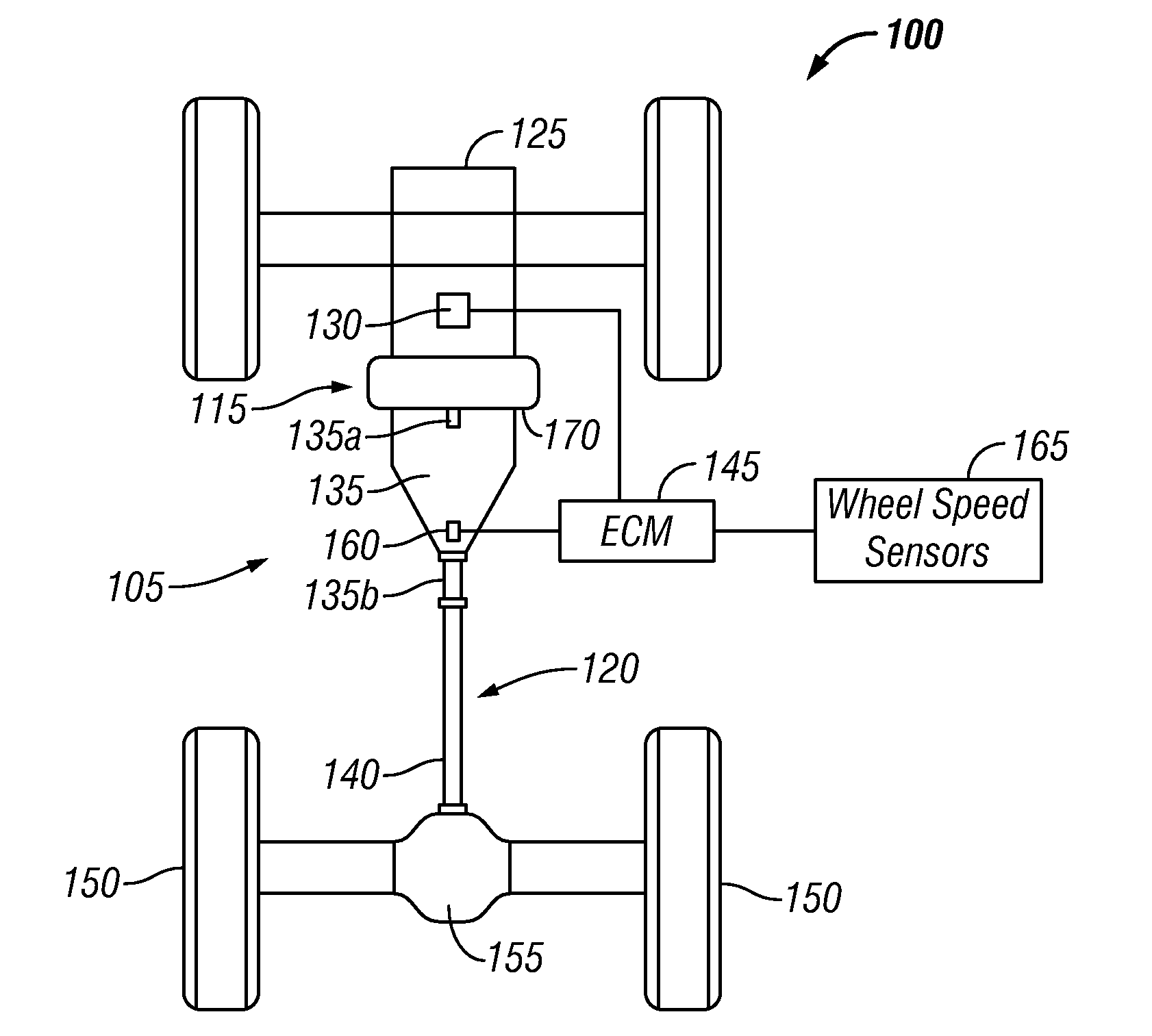
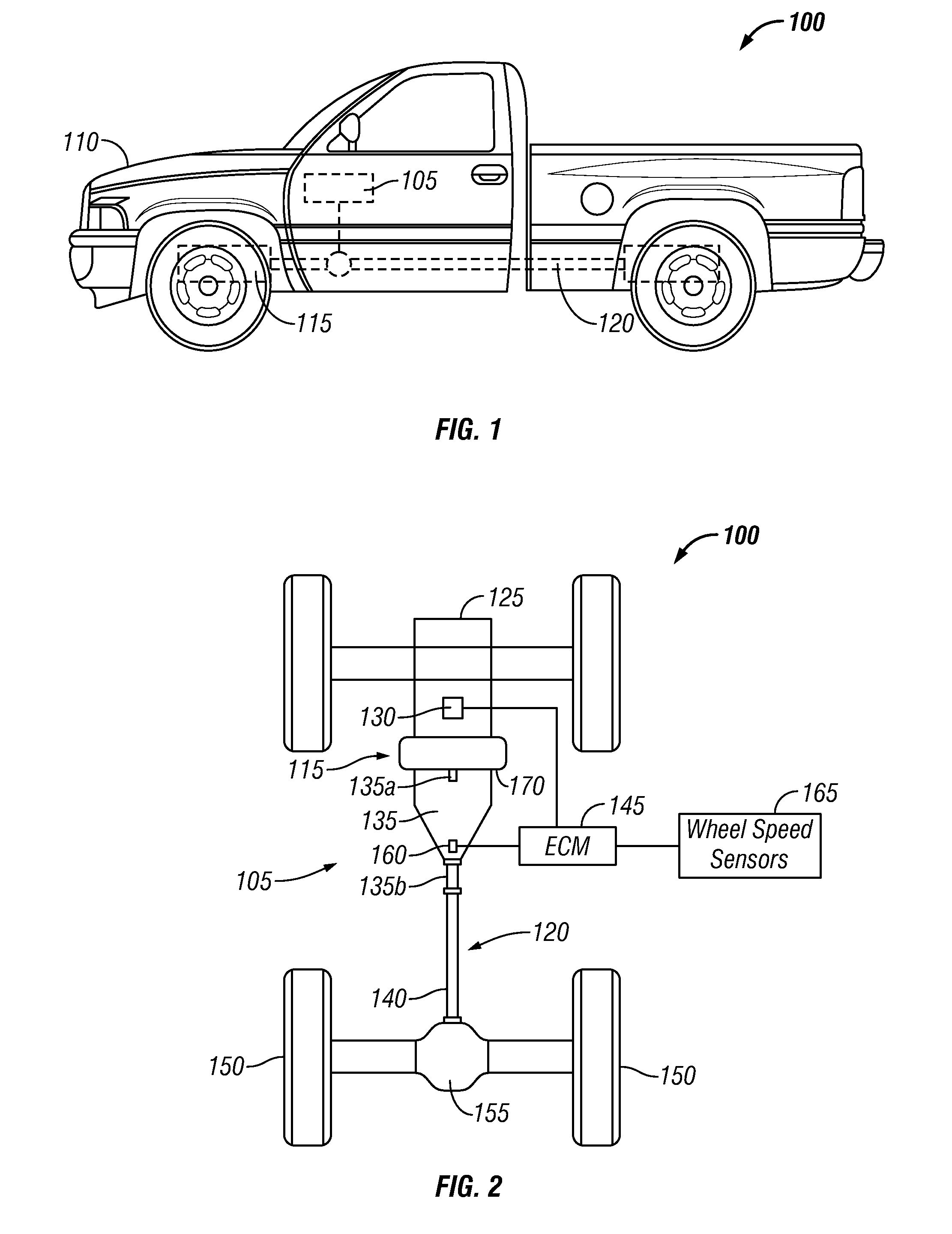
[0017]Referring to FIGS. 1 and 2, a vehicle 100 is illustrated which includes a torque sensor traction control system 105, in accordance with a preferred embodiment. The vehicle 100 generally includes a body 110, a power train 115 and a driveline 120. Note that in FIGS. 1-4, identical parts or elements are generally indicated by the same reference numerals. Note also that the embodiments discussed herein generally relate to a two-wheel drive configuration. It can be appreciated, however, that such embodiments can be implemented in the context of other vehicles having other types of drivelines, including those having more than two drive wheels. The discussion of two-wheel drive configuration, as utilized herein, is presented for general illustrative purposes only.

[0018]Thus, for...


PUM


Abstract

A traction control system that combines torque sensors with wheel speed sensors and a transmission gear with vehicle speed to help sustain maximum traction. The torque sensors generate torque value as output and the speed sensors detect the wheel speed with respect to each wheel of the vehicle. An electronic control module can be utilized to detect traction loss by analyzing the torque and the speed signals and recording the applied torque value when the traction is lost. The torque value can then be limited to a value that is immediately below the recorded torque value in order to prevent further traction loss. The system monitors traction until the speed attains a steady state in order to allow maximum torque and, therefore, maximum acceleration.

Description

TECHNICAL FIELD[0001]Embodiments are generally related to vehicle traction control systems. Embodiments are also related to torque sensors. Embodiments are further related to control techniques for optimizing traction.BACKGROUND OF THE INVENTION[0002]A Traction Control System (TCS) is designed to prevent loss of traction and, therefore, the control of a vehicle when excessive throttle or steering is applied by a driver. Vehicle traction controls can be utilized to sense, for example, wheel slip under non-braking conditions and control one or both of the vehicle brakes or engine to spin down the driven wheels as necessary to regain traction. The wheel spin-up activates the traction control system, which causes a reduction in engine power or a brake activation of the spun-up wheel, which in turn may reduce vehicle performance at a time when it is most demanded. It is undesirable to merely retune the traction control system to ignore the spin-up because the action of the traction contr...

Claims


Application Information

Patent Timeline
Patent Type & Authority Applications(United States)
IPC IPC(8): B60K28/16
CPCB60K28/16B60W2510/1005B60W2710/0666B60W2520/28B60W2520/10
Inventor FOLK, HEATH
Owner HONEYWELL INT INC
Why Eureka
Try Eureka