
Method and appratus for mask pellicle adhesive residue cleaning

a technology of adhesive residue and mask, which is applied in the direction of cleaning using liquids, photosensitive materials, vehicles, etc., can solve the problems of pellicle residue removal, uv lithography, and progressive defect (e.g., haze) remaining on the reticle surface during exposure, and achieves a high degree of automation and control

Inactive Publication Date: 2010-04-01
APPLIED MATERIALS INC
View PDF19 Cites 24 Cited by
  • Summary
  • Abstract
  • Description
  • Claims
  • Application Information

AI Technical Summary

Benefits of technology

[0010]Embodiments of the disclosure generally provide methods and apparatus for cleaning adhesive residue from a photomask substrate. One suitable example of a photomask substrate may be a reticle. In one embodiment, the apparatus includes a processing cell, a support assembly configured to receive a photomask substrate disposed thereon disposed in ...

Problems solved by technology

One significant issue for current deep UV lithography is progressive defect (e.g., haze) remaining on the reticle surface during exposure.
The removal of the pellicle residue is very challenging as remaining pellicle on the reticle may damage the reticle and result in scrapping of the reticle.
The outgased organic compounds may further reduce pellicle transparency, cause pellicle thinning and accelerate pellicle photodegradation.
Thinning of the pellicle 102 may also cause defects or particle contamination on the reticle 110.
Since the adhesive residue 150 may be sticky and viscous, the adhesive residue 150 is difficult to remove from the reticle surface by conventional cleaning techniques, resulting in defects and contamination on the reticle surface.

Method used


Image

  • Method and appratus for mask pellicle adhesive residue cleaning
  • Method and appratus for mask pellicle adhesive residue cleaning
  • Method and appratus for mask pellicle adhesive residue cleaning

Examples


Embodiment Construction

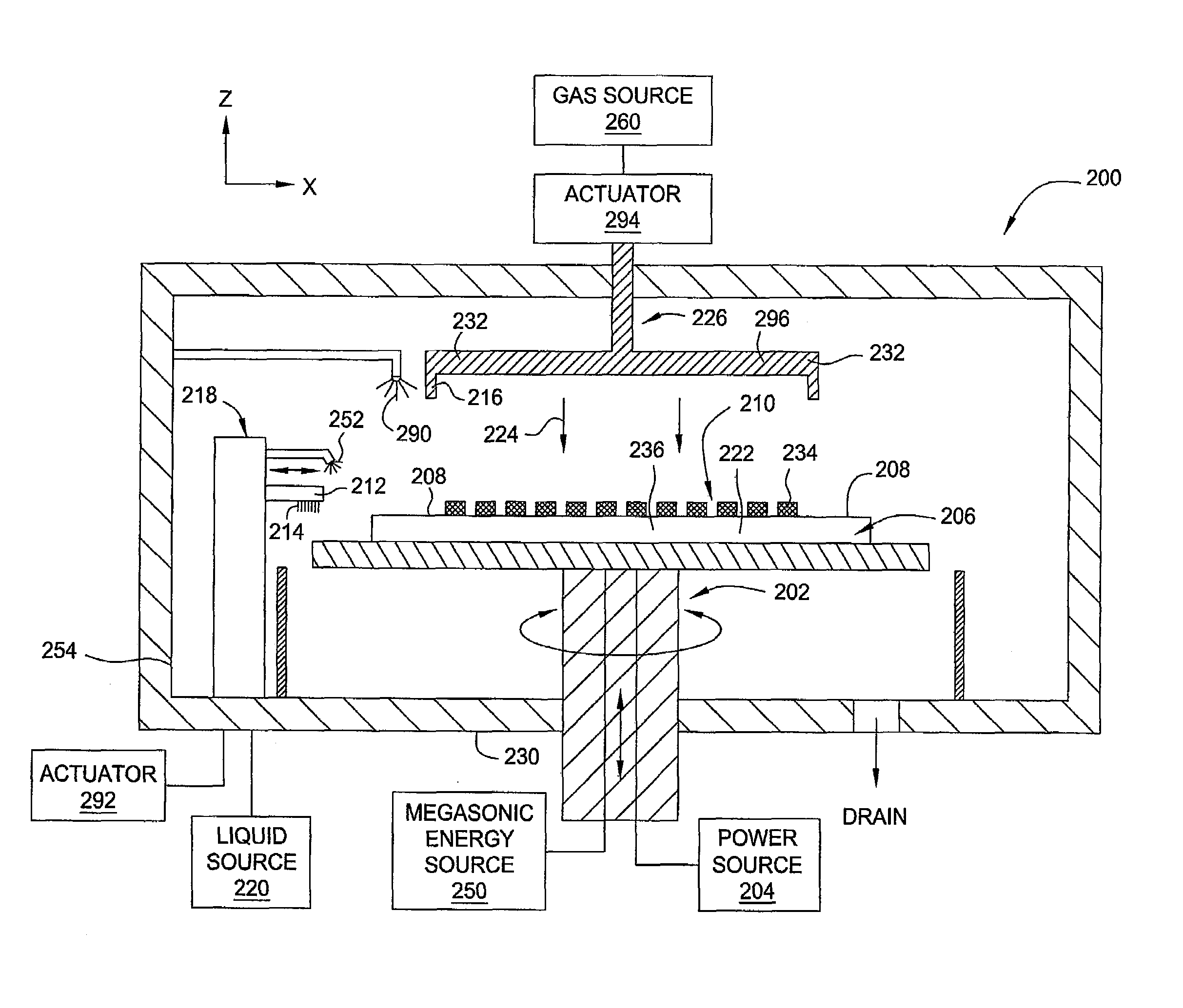
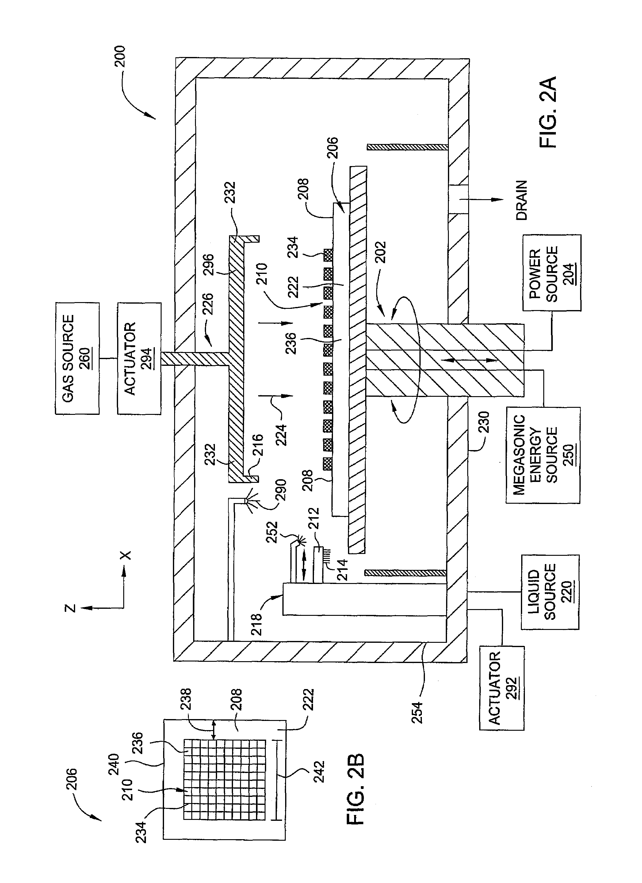
[0023]Embodiments of the disclosure include an apparatus and methods for cleaning adhesive residues and contaminations from a photomask substrate. In one embodiment, the apparatus may clean adhesive residues associated with the use of a pellicle during a photolithography process. In another embodiment, the apparatus may clean other residues, defects, and particles from a photomask substrate. In yet another embodiment, the apparatus may clean residues, defects, and particles from a photomask substrate, particularly residues located at edge or peripheral portion of the photomask substrate.

[0024]FIG. 2A depicts an apparatus suitable for cleaning a photomask substrate 206 in accordance with one embodiment of the present invention. In one embodiment, the photomask substrate 206 may be a recitle, a glass substrate, a transparent substrate, or any other suitable substrates. The apparatus includes a processing cell 200 generally comprising a substrate pedestal 202 and a protection cover ass...


PUM

PropertyMeasurementUnit
Fractionaaaaaaaaaa
Fractionaaaaaaaaaa
Lengthaaaaaaaaaa

Abstract

Aspects of the invention generally provide methods and apparatus for cleaning adhesive residual on a photomask substrate. In one embodiment, the apparatus includes a processing cell, a support assembly configured to receive a photomask substrate disposed thereon disposed in the processing cell, a protection head assembly disposed above and facing the support assembly, and a head actuator configured to control the elevation of the protection head assembly relative to an upper surface of the support assembly. A cleaning device is provided and positioned to interact with the photomask substrate disposed on the support assembly. In another embodiment, a method of cleaning a periphery region of a photomask substrate includes providing a photomask substrate having a periphery portion and a center portion disposed on a support assembly in a processing cell, lowering a protection cover disposed in the processing cell to cover the center portion of the photomask substrate, providing a brush in the processing cell to clean the periphery portion of the photomask substrate.

Description

BACKGROUND[0001]1. Field[0002]The present invention relates to methods and apparatus for cleaning a photolithographic substrate, more particularly, methods and apparatus for cleaning adhesive residue on a photolithographic substrate in the manufacture of integrated circuits.[0003]2. Background of the Related Art[0004]The increasing circuit densities have placed additional demands on processes used to fabricate semiconductor devices. For example, as circuit densities increase, the widths of vias, contacts and other features, as well as the dielectric materials between them, decrease to sub-micron dimensions, whereas the thickness of the dielectric layers remains substantially constant, with the result that the aspect ratios for the features, i.e., their height divided by width, increases. Reliable formation of high aspect ratio features is important to the success of sub-micron technology and to the continued effort to increase circuit density and quality of individual substrates.[00...

Claims


Application Information

Patent Timeline
IPC IPC(8): B08B1/04B01J19/08A46B9/02A46B11/06
CPCB08B1/00G03F1/82B08B11/02B08B3/02Y10S134/902
Inventor WU, BANQIULEE, RICHARDYALAMANCHILI, M. RAOKUMAR, AJAYPAPANU, JAMES S.JEON, CHUNG-HUAN
Owner APPLIED MATERIALS INC
Features
  • Generate Ideas
  • Intellectual Property
  • Life Sciences
  • Materials
  • Tech Scout
  • Unparalleled Data Quality
  • Higher Quality Content
  • 60% Fewer Hallucinations
Learn More