Spacers for Microfluidic Channels

a microfluidic channel and spacer technology, applied in the direction of diaphragm valves, laboratory glassware, engine diaphragms, etc., can solve the problems of difficult to locate an individual plug within a sequence of plugs, change the size of plugs, and undesirable manipulation of interfaces for some applications

Inactive Publication Date: 2010-04-01
UNIVERSITY OF CHICAGO
View PDF27 Cites 20 Cited by
  • Summary
  • Abstract
  • Description
  • Claims
  • Application Information

AI Technical Summary

Benefits of technology

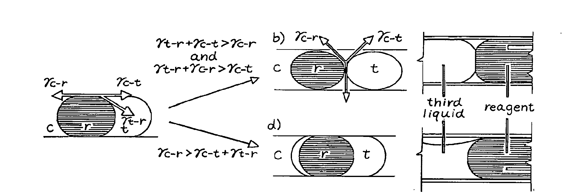
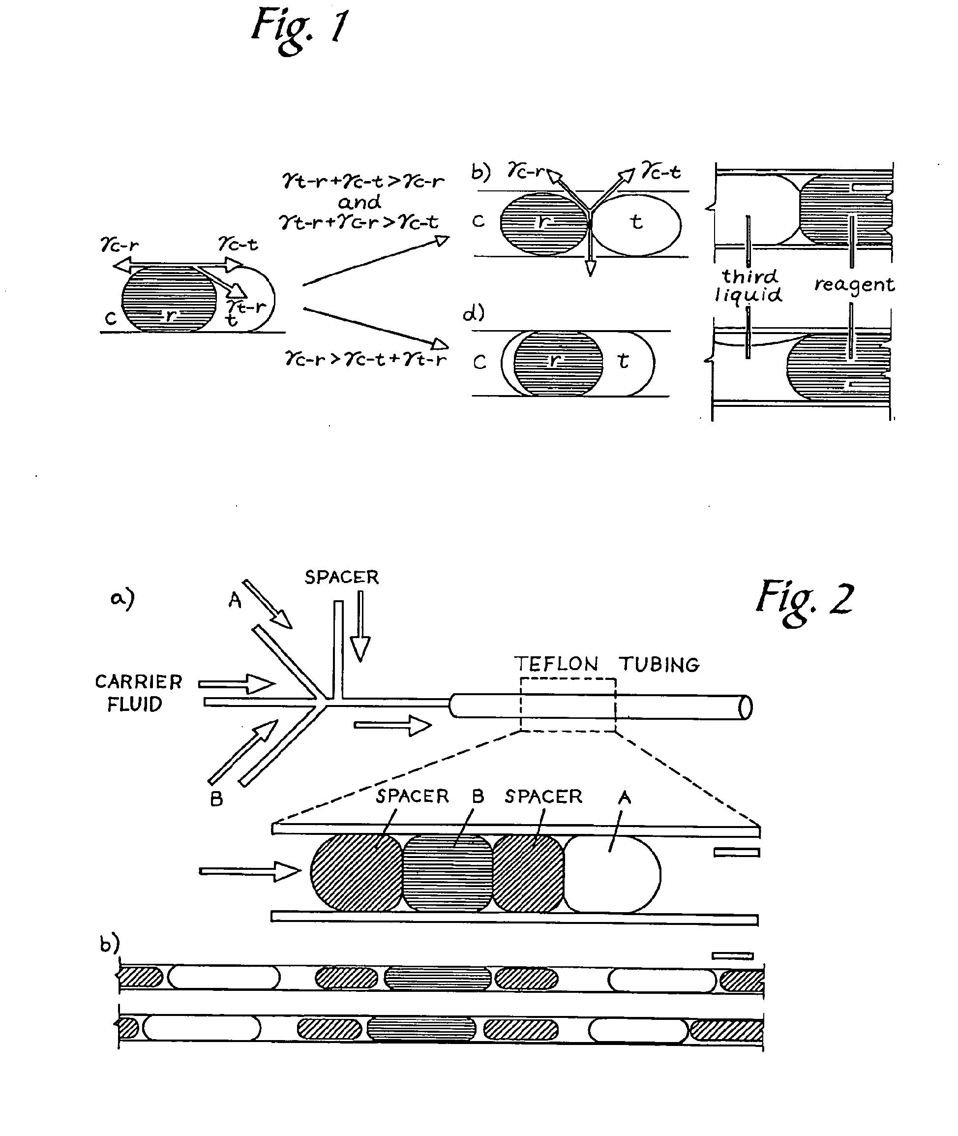
[0007]In one embodiment, a microfluidic system comprises a microchannel, a carrier fluid in the microchannel, and at least two plugs in the microchannel. Each plug comprises a plug fluid that is substantially immiscible with the carrier fluid. The microfluidic system further comprises at least one spacer in the microchannel between two plugs. Each spacer comprises a spacer fluid that is substantially immiscible with the carrier fluid and the plug fluid, and both of the following conditions are satisfied: (γc-r+γt-r>γc-t) and (γc-t+γt-r>γc-r), where γc-r is the interfacial force between the carrier fluid and the plug fluid, γt-r is the interfacial force between the spacer fluid and the plug fluid, and γc-t is the interfacial force between the carrier fluid and the spacer fluid.

Problems solved by technology

Coalescence of neighboring plugs, however, can cause contamination of reagents, change the size of plugs, and make it difficult to locate an individual plug within a sequence of plugs.
Coalescence may be suppressed by loading the liquid-liquid interfaces with detergents or colloidal particles, but this manipulation of interfaces may be undesirable for some applications.
For applications involving long arrays of plugs, there are two drawbacks in using gas bubbles as spacers.
First, compressible gas bubbles could cause flow fluctuation and a lag in response to the change of flow rates in pressure-driven flow.
Second, gas bubbles may dissolve in a fluorinated carrier fluid under high pressure.

Method used


Image

  • Spacers for Microfluidic Channels
  • Spacers for Microfluidic Channels
  • Spacers for Microfluidic Channels

Examples


example

[0050]Materials. The glycerol solutions were made in water, and the percentage concentrations were by volume unless otherwise stated. The three carrier fluids were fluorocarbons used with or without the surfactant 1,1,2,2-tetrahydroperfluorooctanol (PFO), provided by Alfa Aesar, MA: (1) FC40, provided by Acros Organics, NJ; (2) FC70; and (3) FC3283, both provided by 3M, MN. 1,3-Diphenyl-1,1,3,3-tetramethyldisiloxane (SID) was purchased from Gelest, PA. Dimethyl tetrafluorosuccinate (DTFS) was obtained from Synquest, FL. Protein Tdp1 (N-terminal truncation (Δ1-148) of the human tyrosyl-DNA phosphodiesterase with an N-terminal His-tag, expressed in Escherichia coli) was provided by deCODE Biostructures, WA. The protein solution was provided frozen, at a concentration of about 6.7 mg / mL in a buffer containing about 250 mM NaCl, about 15 mM Tris (pH about 8.2), and about 2 mM Tris(2-carboxyethyl)-phosphine (TCEP). A detailed description of the protein expression and purification can be ...


PUM


Abstract

A microfluidic system comprises a microchannel, a carrier fluid in the microchannel, and at least two plugs in the microchannel. Each plug comprises a plug fluid that is substantially immiscible with the carrier fluid. The microfluidic system further comprises at least one spacer in the microchannel between two plugs. Each spacer comprises a spacer fluid that is substantially immiscible with the carrier fluid and the plug fluid, and both of the following conditions are satisfied: (γc-rt-rc-t) and (γc-t+yt-r>yc-r), where γc-r is the interfacial force between the carrier fluid and the plug fluid, γt-r is the interfacial force between the spacer fluid and the plug fluid, and γc-t is the interfacial force between the carrier fluid and the spacer fluid.

Description

[0001]The present application claims priority to U.S. Provisional Patent Application Ser. No. 60 / 875,856, filed Dec. 19, 2006, the entirety of which is hereby incorporated by reference.[0002]This invention was made with government support under grant number DMR0213745 awarded by the National Science Foundation (NSF) and grant number GM074961 awarded by the National Institutes of Health (NIH). The government has certain rights in the invention.FIELD OF THE INVENTION[0003]The present invention relates to spacers for microfluidic channels. More particularly, the present invention relates to using three-phase flow of immiscible liquids or hydrophobic particles to prevent coalescence of droplets in microfluidic channels.BACKGROUND OF THE INVENTION[0004]Discrete microfluidic plugs (droplets large enough to fill the cross section of a microfluidic channel) dispersed in an immiscible carrier fluid have been used in protein crystallization, synthesis of microparticles (including vesicles and...

Claims


Application Information

Patent Timeline
Patent Type & Authority Applications(United States)
IPC IPC(8): F16K99/00
CPCB01L3/502784B01L2200/0668B01L2400/0487B01L2300/0864B01L2200/0673Y10T137/0318Y10T137/877
Inventor ISMAGILOV, RUSTEM F.CHEN, DELAI L.LI, LIANGDU, WENBIN
Owner UNIVERSITY OF CHICAGO
Why Eureka
Try Eureka