Light Emitting Apparatus

a technology of light emitting apparatus and fluorescent lamps, which is applied in the direction of lighting and heating apparatus, lighting support devices, instruments, etc., can solve the problem of low energy efficiency

Active Publication Date: 2010-04-01
SUZHOU LEKIN SEMICON CO LTD
View PDF3 Cites 92 Cited by
  • Summary
  • Abstract
  • Description
  • Claims
  • Application Information

AI Technical Summary

Benefits of technology

[0009]Embodiments provide a fluorescent lamp type light emitting apparatus that

Problems solved by technology

Illuminators, such as incandescent lamps, fluorescent lamps and three-wavelength lamps are convenient to manufacture a

Method used


Image

  • Light Emitting Apparatus
  • Light Emitting Apparatus
  • Light Emitting Apparatus

Examples


Embodiment Construction

[0021]Reference will now be made in detail to embodiments of the present disclosure, examples of which are illustrated in the accompanying drawings.

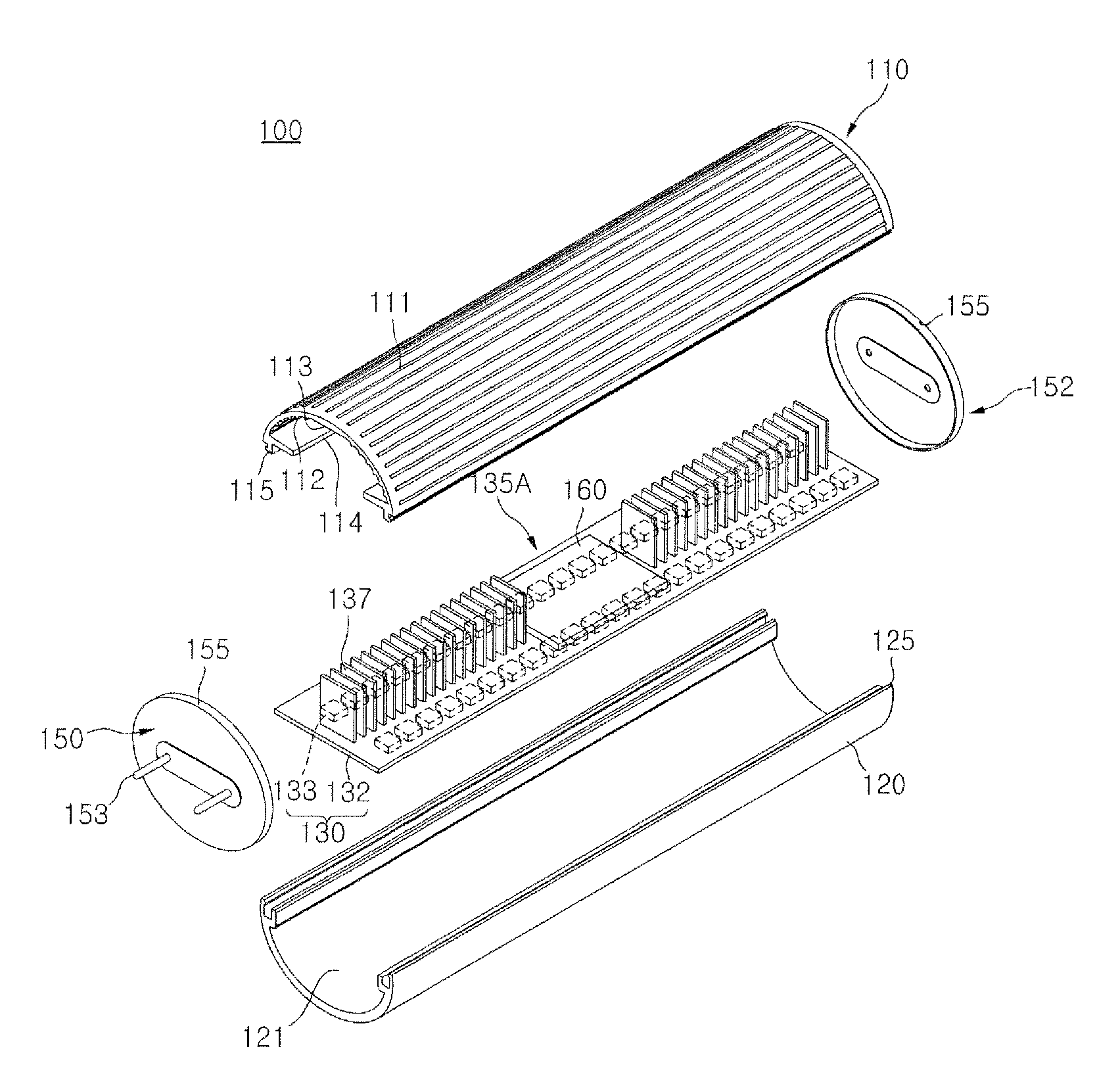
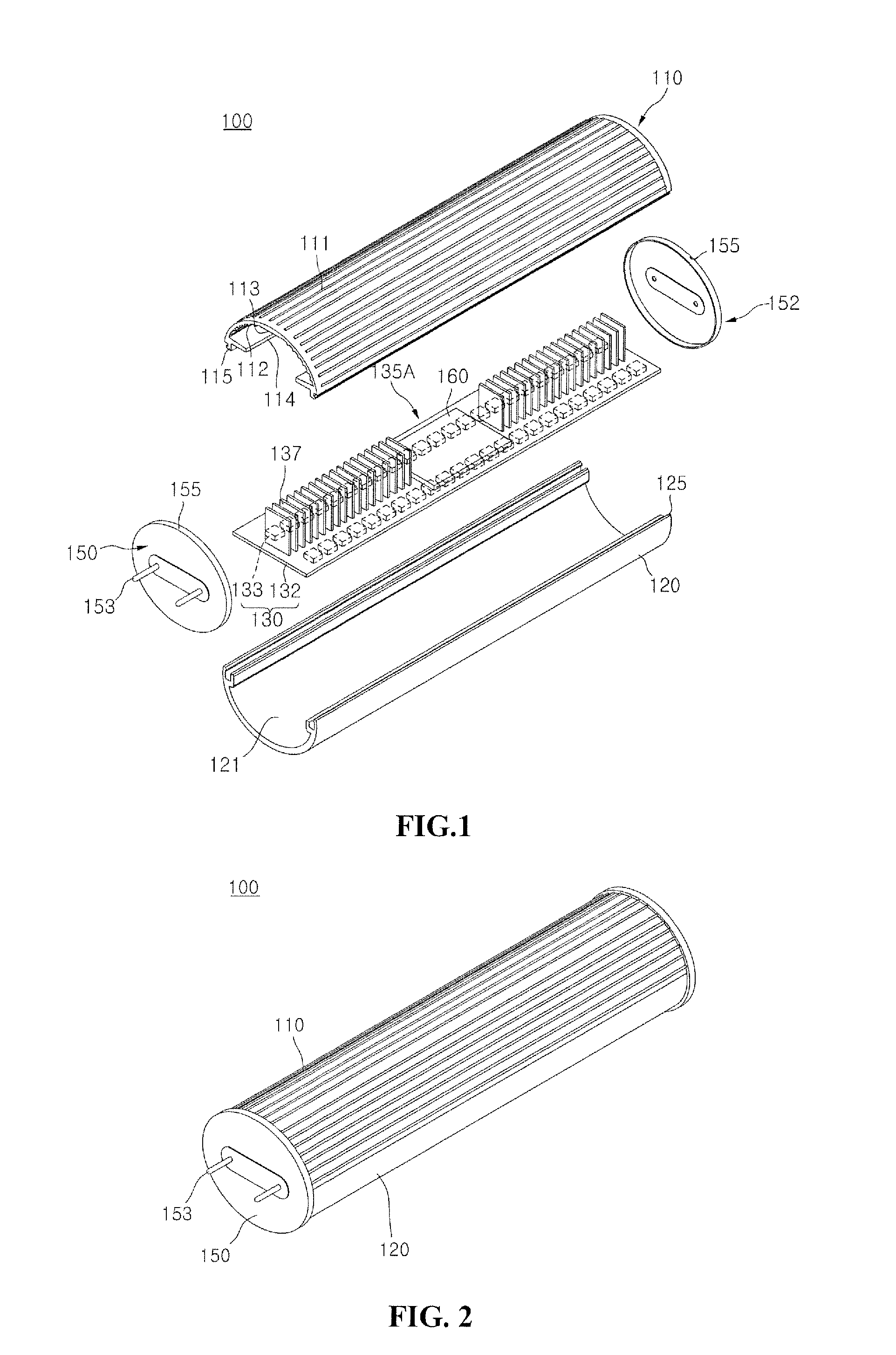
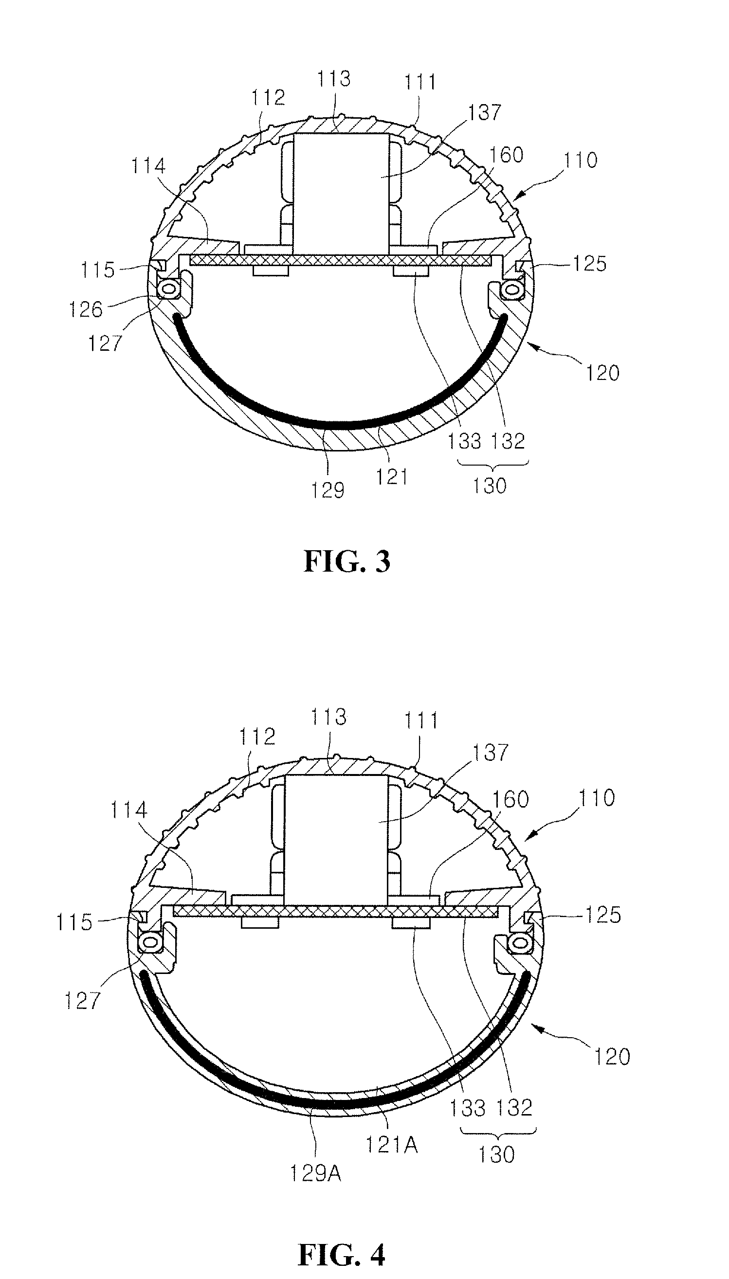
[0022]FIG. 1 is an exploded perspective view illustrating a fluorescent lamp type light emitting apparatus 100 according to an embodiment, FIG. 2 is a perspective view illustrating the fluorescent lamp type light emitting apparatus 100 of FIG. 1, and FIG. 3 is a cross-sectional view illustrating the fluorescent lamp type light emitting apparatus 100 of FIG. 2.

[0023]Referring to FIG. 1, the light emitting apparatus 100 comprises a first cover 110, a second cover 120, a light emitting module 130, and cap parts 150.

[0024]The light emitting apparatus 100 may be defined as a straight pipe type cylindrical lamp, a straight pipe type rod lamp, a straight pipe type tube lamp, or a tube type lamp. Hereinafter, the light emitting apparatus 100 will be described as a straight pipe type cylindrical lamp for convenience in description.

[0025]The first...


PUM


Abstract

A fluorescent lamp type light emitting apparatus is provided. The light emitting apparatus comprises a cover, a light emitting module, radiation pads, and cap parts. The cover comprises a first cover and a transmissive second cover coupled to the first cover. The light emitting module comprises a plurality of light emitting diodes in the cover. The radiation pads are disposed on the light emitting module. The cap parts comprise electrode terminals at both ends of the cover.

Description

CROSS-REFERENCE TO RELATED APPLICATION[0001]This application claims the benefit under 35 U.S.C. §119 of Korean Patent Application No. 10-2008-0095451, filed Sep. 29, 2008, which is hereby incorporated by reference in its entirety.BACKGROUND[0002]The present disclosure relates to a fluorescent lamp type light emitting apparatus.[0003]Research and development on illuminators has been carried out to improve energy efficiency and satisfy requirements of users. Illuminators, such as incandescent lamps, fluorescent lamps and three-wavelength lamps are convenient to manufacture and use, and are thus very popular, but they are uneconomical due to their short service life and low energy efficiency. To address this limitation, light emitting diode (LED) illuminators, which have improved service life and energy efficiency, have been developed and sold.[0004]Such LED illuminators have 25 W or lower power consumption, and may reduce electricity fees by about 30% or more. In addition, since LED i...

Claims


Application Information

Patent Timeline
IPC IPC(8): H05B37/02F21S4/00F21V9/00F21V1/00H05B44/00
CPCF21K9/17F21V29/87F21V3/02F21V17/104F21V17/164F21V29/004F21Y2101/02F21Y2103/003F21Y2105/001H05B33/0803Y02B20/383Y02B20/386F21V29/22F21V29/763F21S4/003F21V29/507F21S4/20F21Y2105/10F21K9/27F21Y2103/10F21Y2115/10F21K9/66Y02B20/30H05B45/34H05B45/42H05B45/3578F21V29/89F21K9/275F21V23/02F21V29/80F21V19/008
Inventor SON, WON JIN
Owner SUZHOU LEKIN SEMICON CO LTD
Why Eureka
Try Eureka