
Modular System for Diagnosis and Surgical Operation on a Breast

a breast and module technology, applied in the field of breast x-ray machine, can solve the problems of large space requirement, lack of access to the breast to be examined, patient placed in a relatively uncomfortable position, etc., and achieve good and ergonomically advantageous access to the breast. , the effect of favorable cos

Inactive Publication Date: 2010-04-01
MIR MEDICAL IMAGING RES HLDG
View PDF47 Cites 20 Cited by
  • Summary
  • Abstract
  • Description
  • Claims
  • Application Information

AI Technical Summary

Benefits of technology

[0007]The objective of the disclosure provided herein is to design an X-ray machine which images a female breast in a diagnostically correct manner, and also rapidly and at favorable cost, and at the same time makes it possible to perform a surgical operation or intervention on the breast. In addition, the machine is to provide a physician performing treatment with good and ergonomically advantageous access to the breast.
[0008]An embodiment of an X-ray machine for imaging a breast of a female patient and performing surgical intervention on the breast includes a gantry that is rotatable approximately about a vertical rotation axis and a gantry lift drive configured to move the gantry in a vertical direction, wherein a vertical movement of the gantry is dependent upon the rotational movement of the gantry. The X-ray machine further includes an X-ray tube and an X-ray detector mounted on the gantry and a horizontally disposed patient's table having a cutout portion for a breast, wherein the gantry is suspended from a lower side of the patient's table. In addition, the X-ray machine includes an instrument holder for accommodating at least one operating instrument in the vicinity of the breast through the gantry from below the patient's table so that surgical intervention can be effected with the operating instrument.

Problems solved by technology

A disadvantage of this prior art is the large requirement of space, and also the lack of access to a breast to be examined.
Furthermore, the patient is put into a relatively uncomfortable position with her head lying low, in order that as large as possible a part of the breast can be covered by the X-ray machine.
A disadvantage of this arrangement is the large requirement of space resulting from the large structural shape of the gantry.
Here, the resolution is limited by low stability of the mechanical design.
In addition, here too the breast to be examined cannot be accessed from outside.

Method used


Image

  • Modular System for Diagnosis and Surgical Operation on a Breast
  • Modular System for Diagnosis and Surgical Operation on a Breast
  • Modular System for Diagnosis and Surgical Operation on a Breast

Examples


Embodiment Construction

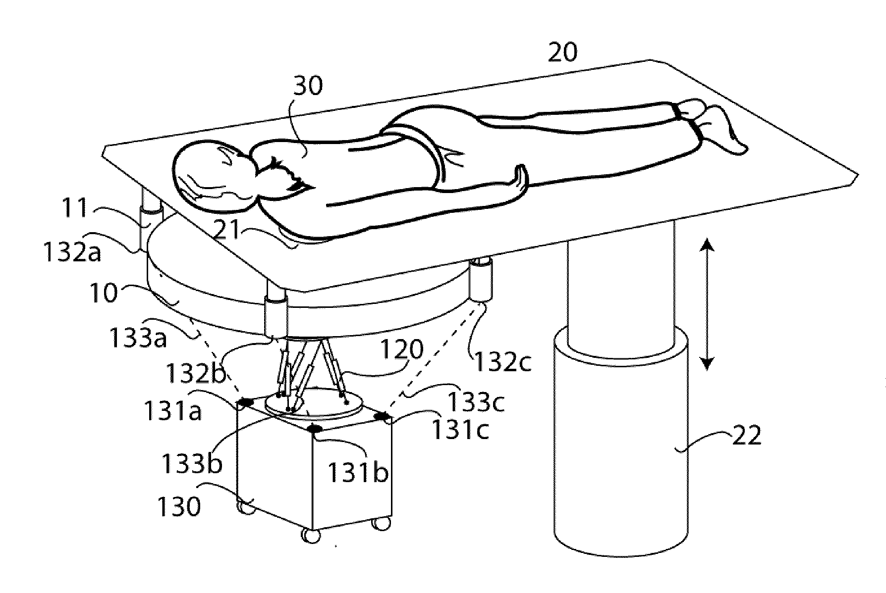
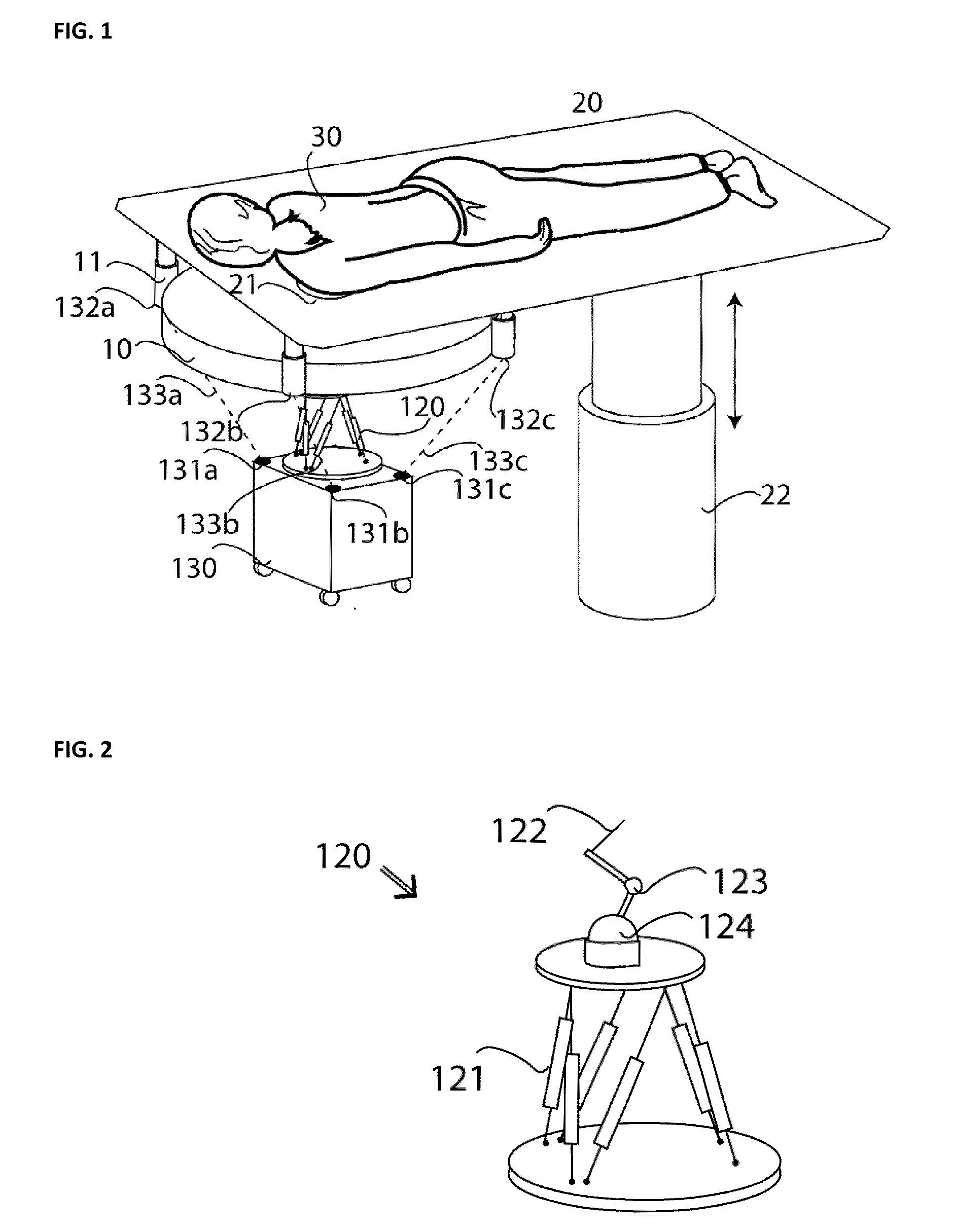
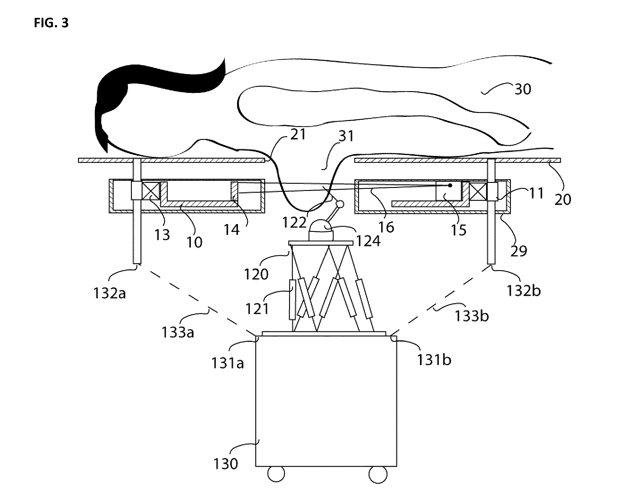
[0016]FIG. 1 shows perspective view of an example of an X-ray machine. A patient 30 is positioned on a patient's table 20. A breast to be examined is suspended through a breast cutout portion 21 in the patient's table into an exposure range of a gantry 10. The gantry 10 is a spiral computer tomography gantry with an X-ray tube and a detector which rotate about the breast to be examined. During the rotation, the breast is imaged, i.e. exposed to X-rays to obtain X-ray images. Simultaneously with the rotation, a displacement of the gantry in a vertical direction is performed via a gantry lift drive 11 so that the breast is scanned along a spiral trajectory. The height of the patient's table 20 can be adjusted by means of a patient's table lift drive 22. In a case in which a patient's table is firmly installed, it can be optionally adapted to be rotated about an axis of the patient's table lift drive 22.

[0017]A mobile platform 130 is located below the gantry 10. During an examination, ...


PUM


Abstract

An X-ray machine for examining a breast of a female patient has a CT scanner attached to a patient's table. An instrument holder that is adapted to be moved to be located underneath a gantry of the CT scanner is provided with a positioning unit for positioning an instrument for examining or operating close to the breast. An exact position of the instrument holder relative to the gantry or the breast to be examined can be determined with a measuring system. Thereby, it is possible to position an examining or surgical intervention instrument extremely precisely.

Description

PRIORITY CLAIM[0001]This application claims priority to pending German Application No. 102008042430.7 filed on Sep. 29, 2008.BACKGROUND OF THE INVENTION[0002]1. Field of the Invention[0003]The invention relates to an X-ray machine for imaging a breast of a female patient. With this machine it is possible to perform a surgical operation on a breast.[0004]2. Description of Related Art[0005]Various X-ray machines are known for performing an examination of a female breast. An X-ray facility having a rotating gantry with an X-ray tube and a detector is located below a patient's table on which a patient to be examined rests. A machine of this kind is disclosed for example in U.S. Pat. No. 4,015,836. A disadvantage of this prior art is the large requirement of space, and also the lack of access to a breast to be examined. Furthermore, the patient is put into a relatively uncomfortable position with her head lying low, in order that as large as possible a part of the breast can be covered b...

Claims


Application Information

Patent Timeline
IPC IPC(8): A61B6/04
CPCA61B5/015A61B6/027A61B5/704A61B6/032A61B6/035A61B6/0435A61B6/06A61B6/107A61B6/502A61B6/583A61B18/00A61B2017/00084A61B2019/205A61B2019/5238A61B2019/524G01K11/30G06T7/0012G06T7/0083G06T2207/10081G06T2207/30068G06T2207/30096A61B5/4312A61B6/4275A61B90/17A61B2090/376A61B2090/3762G06T7/74G06T7/12
Inventor KALENDER, WILLISCHILLING, HARRY
Owner MIR MEDICAL IMAGING RES HLDG
Learn More