Temperature sensing

a technology of sensing and temperature, applied in the field of sensing temperature, can solve the problems of multiple wires and connections, wiring replacement, wiring damage, etc., and achieve the effect of more accurate sensing of temperature, easy to make, and easy association with a structur

Active Publication Date: 2010-04-01
GKN AEROSPACE SERVICES LTD
View PDF17 Cites 15 Cited by
  • Summary
  • Abstract
  • Description
  • Claims
  • Application Information

AI Technical Summary

Benefits of technology

[0008]This provides a simple construction which is easily made, is compact and can easily be associated with a structure in an appropriate location at which a temperature measurement is to be made. The housing may be of any suitable material allowing compatibility with any particular application of the sensor or sensor array. The housing isolates the grating from strain imposed on the fibre outside the housing allowing more accurate sensing of temperature and allowing the apparatus to be set up easily without the need to ensure the fibre outside the housing is unstrained (except for avoiding breakage of the fibre).

Problems solved by technology

A single thermocouple monitors only a localised area and many thermocouples are needed on a larger tool resulting in multiple wires and connections.
Furthermore, thermocouples and their wiring may embed themselves into the material being formed resulting in damage to, and replacement of, wiring after the composite material has been removed from the tool, and recalibration of the thermocouples if they are reused.
The glass tube also reduces the sensitivity of the grating to axial strain on the fibre outside the tube.
However, because the tube is fused to the fibre, axial strain on the fibre is transmitted to the fibre within the tube so the value sensed by the grating within the tube is not independent of axial strain on the fibre.
This strain isolating package has the disadvantages that it is relatively large and further involves the optical fibre intersecting, or crossing over, itself where the optical fibre enters and leaves the circular groove.

Method used


Image

  • Temperature sensing
  • Temperature sensing
  • Temperature sensing

Examples


Embodiment Construction

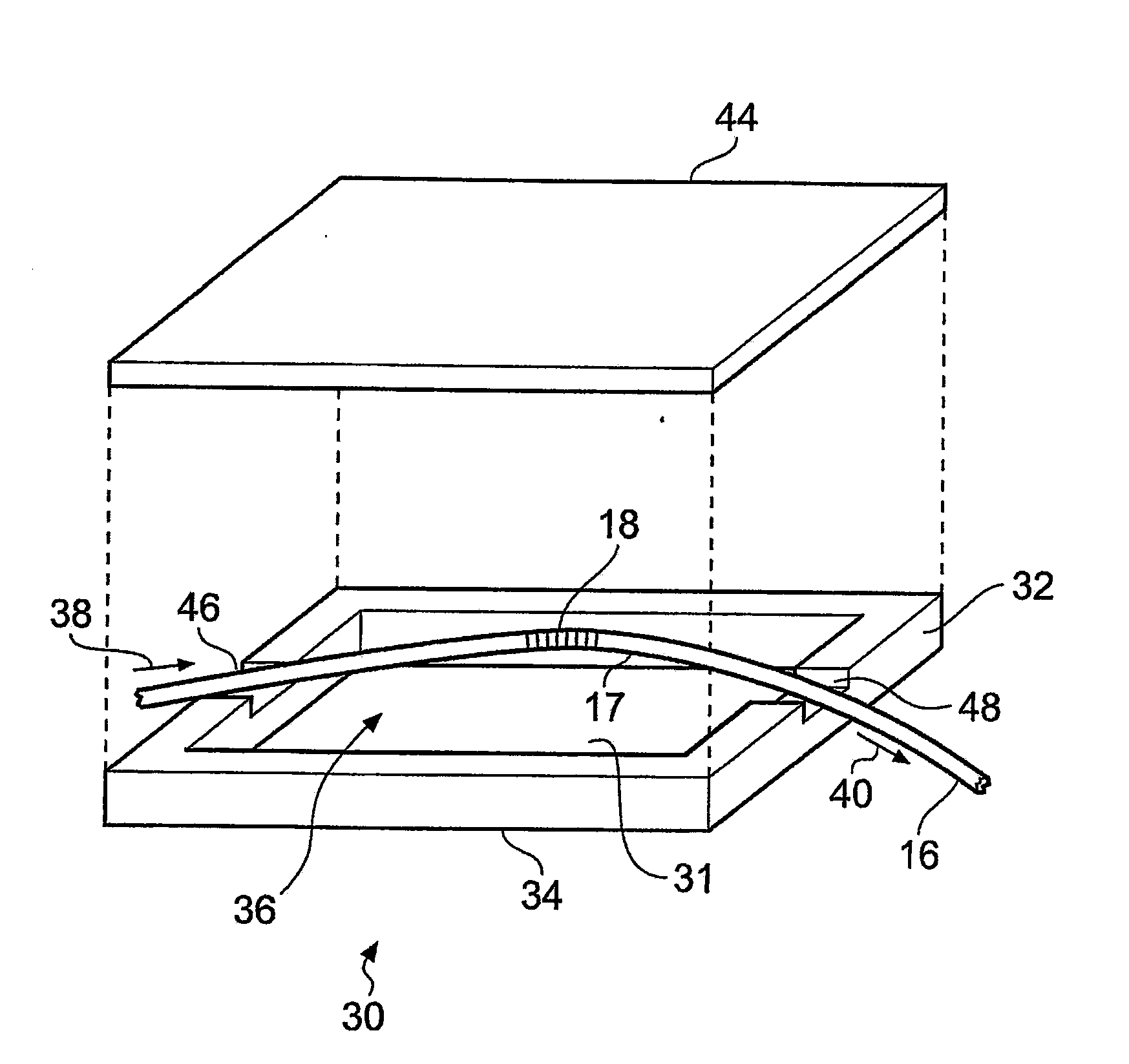
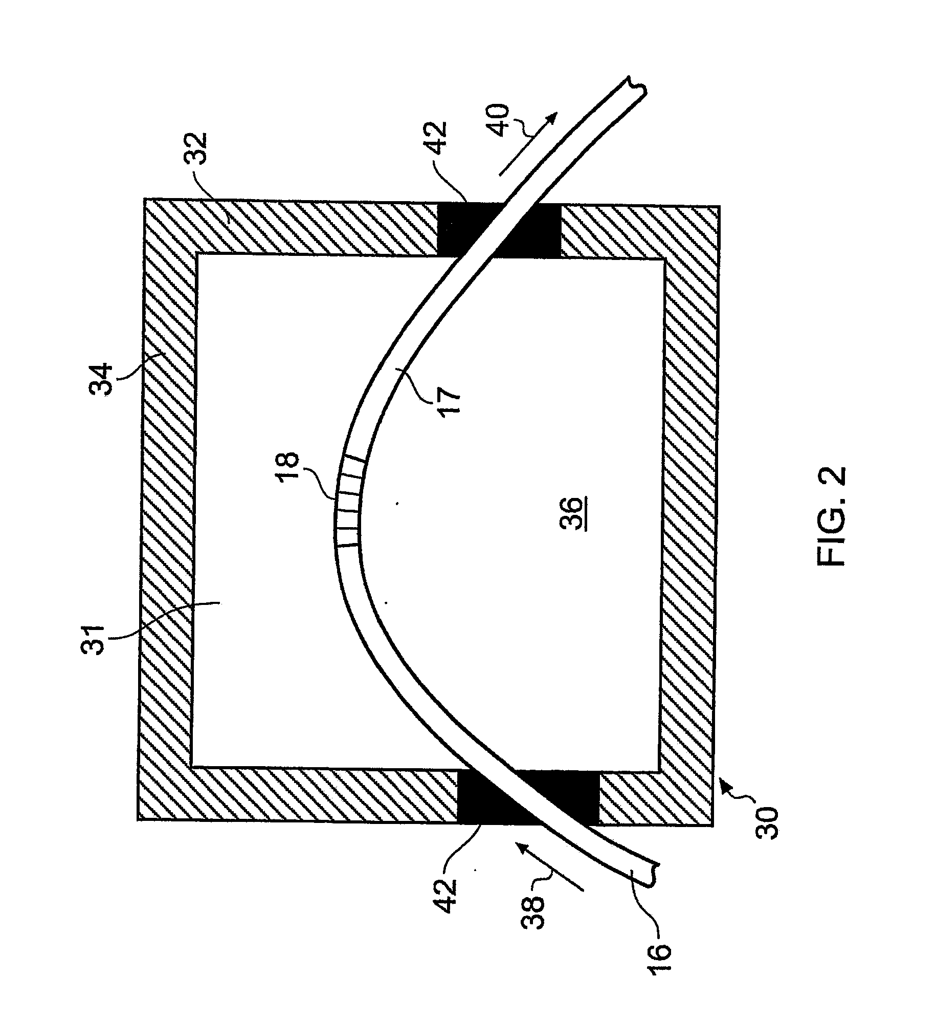
[0029]Embodiments of the invention will be described with reference to a tool for forming a component of composite material for example a laminated material made of pre-impregnated reinforcement fibre in a polymeric resin.

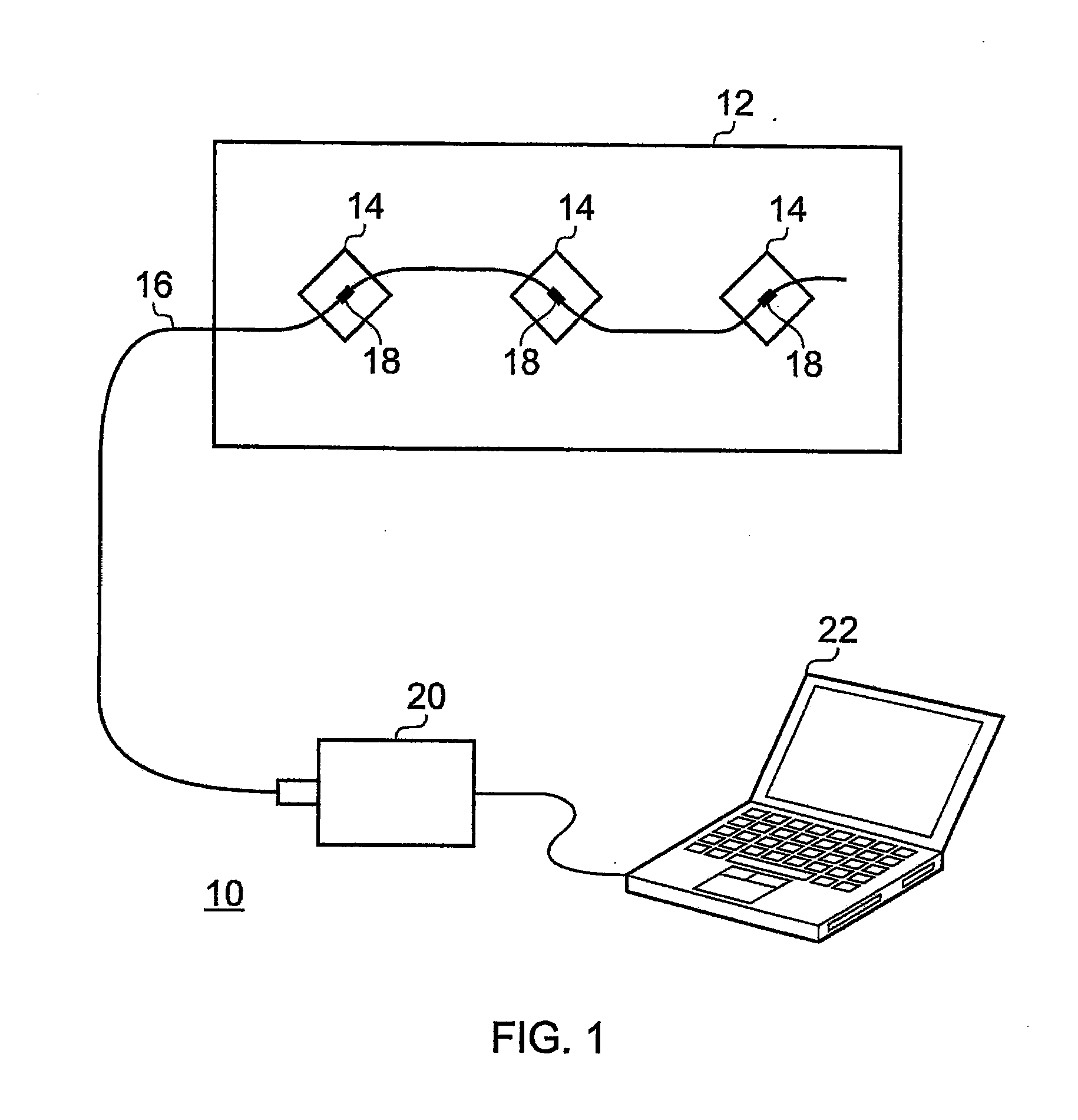
[0030]Each lamina of the laminated material can include plies of fibres. The fibres may be carbon fibres or Kevlar for example. The fibres of successive laminae may be differently oriented as known in the art. The process of forming the component requires the tool to be heated by one or more heaters which may be embedded in the tool. The temperature of the tool needs to be at least monitored and preferably controlled and for that purpose an array of temperature sensors is provided. In this example, the array comprises many sensors on a single optical fibre.

[0031]The tool can be of a material compatible with the composite material being formed. For example, in the described examples, the tool is of the same material as the composite.

[0032]The optical fibre can be ma...


PUM

PropertyMeasurementUnit
thicknessaaaaaaaaaa
length×width×heightaaaaaaaaaa
lengthaaaaaaaaaa

Abstract

A temperature sensor array comprises an optical fibre (16) on which are a plurality of Bragg gratings (18) on respective spaced apart portions of the fibre. Each portion is in a housing (14) which freely houses the said portion substantially without axial strain on the fibre within the housing and which also isolates the grating from strain imposed on the fibre outside the housing. Thus substantially only changes in temperature affect the Bragg grating of that portion. The array may be used to detect and control the temperature of a tool (12) for forming a composite component amongst other uses.

Description

BACKGROUND[0001]The present invention relates to sensing temperature, for example for a tool for forming a composite component.[0002]It is known to make composite components of composite materials using a tool having one or more heaters embedded in the tool. It is necessary to monitor and / or control the temperature of the tool during a cure cycle. Normally thermocouples have been used but they have several disadvantages. A single thermocouple monitors only a localised area and many thermocouples are needed on a larger tool resulting in multiple wires and connections. Normally, thermocouples are placed just outside the edge of the component being formed in “spare” material which is removed from the component after it is formed. Furthermore, thermocouples and their wiring may embed themselves into the material being formed resulting in damage to, and replacement of, wiring after the composite material has been removed from the tool, and recalibration of the thermocouples if they are r...

Claims


Application Information

Patent Timeline
Patent Type & Authority Applications(United States)
IPC IPC(8): G02B6/44G02B6/10G01K11/32B23P21/00
CPCG01D5/35383G01D11/245Y10T29/53039G01K11/3206G01K1/20G01D5/35316G01D5/35387
Inventor SAUNDERS, PAUL VINCENTMARENGO, GIOVANNI ANTONIO
Owner GKN AEROSPACE SERVICES LTD
Why Eureka
Try Eureka