System and Method for Adjusting Selected Operating Parameters of Image Forming Device Based on Selected Environmental Conditions to Improve Color Registration

an image forming device and operating parameter technology, applied in the field of ep image forming devices, can solve the problems of large difference between the potential of the developer roll and the charge on the pc drum surface, the failure of the interface between the developer roll and the pc drum, and the inability to control tolerances and wear, etc., to achieve better print quality and color registration, improve color registration, and optimize the voltage of the charge roll

Active Publication Date: 2010-04-01
LEXMARK INT INC
View PDF4 Cites 12 Cited by
  • Summary
  • Abstract
  • Description
  • Claims
  • Application Information

AI Technical Summary

Benefits of technology

[0012]The present invention meets this need by providing an innovation directed toward adjusting certain selected operating parameters, namely, bias voltages applied to the charge roll and developer roll, based on wet-bulb temperature values derived from dry-bulb temperature and relative humidity readings from sensors of current environmental conditions, in place of cold start servo voltage values as practiced heretofore. These adjustments will allow for better charge roll voltage optimization and thus better print quality and color registration.
[0013]Accordingly, in an aspect of the present invention, a system for adjusting selected operating parameters of an image forming device based on selected environmental conditions to improve color registration includes a first image forming station to print a first registration mark on a substrate, a second image forming station having a photoconductive unit, a charging unit and a developer unit cooperable together so as to at least partially erase the first registration mark printed on the substrate by the first image forming station to form a registration pattern in a reverse transfer process of the color registration, a sensor mechanism for measuring selected environmental conditions of dry-bulb temperature and relative humidity, a control mechanism for reading the sensor mechanism to adjust the voltage biases of the charging and developer units of the second image forming station based on a wet-bulb temperature value so as to maintain a predetermined potential difference between charged and uncharged areas of the photoconductive unit of the second image forming station that avoids Paschen breakdown and the development of toner at charged areas of the photoconductive unit during the reverse transfer process of the color registration, and a memory connected to and accessible by the control mechanism and having a lookup table stored therein containing lists of correlated values comprising a list of wet-bulb temperature values related to values of dry-bulb temperature and relative humidity measured by the sensor mechanism correlated with lists of voltage values related to voltage biases of the charging and developer units to maintain the predetermined potential difference between the charged and uncharged areas of the photoconductive unit during the reverse transfer process of the color registration.
[0014]In another aspect of the present invention, a method for adjusting selected operating parameters of an image forming device based on selected environmental conditions to improve color registration includes at a first image forming station printing a first registration mark on a substrate, at a second image forming station at least partially erasing the first registration mark printed on the substrate by the first image forming station to form a registration pattern in a reverse transfer process of the color registration performed at the second image forming station, sensing selected environmental conditions of dry-bulb temperature and relative humidity so as to determine wet-bulb temperature values correlated with the dry-bulb temperature and relative humidity, and adjusting voltage biases of charge and developer rolls of the second image forming station based on the wet-bulb temperature value so as to maintain a predetermined potential difference between charged and uncharged areas of a photoconductive unit of the second image forming station that avoids Paschen breakdown and the development of toner at charged areas of the photoconductive unit during the reverse transfer process of the color registration. The method further includes storing a lookup table in memory containing lists of correlated values comprising a list of wet-bulb temperature values related to values of sensed dry-bulb temperature and relative humidity correlated with lists of voltage values related to voltage biases of the charging and developer units to maintain the predetermined potential difference between the charged and uncharged areas of the photoconductive unit during the reverse transfer process of the color registration.

Problems solved by technology

It can be expensive and impractical to control tolerances and wear in order to provide acceptable color registration.
However, because the developer roll bias in the “reverse transfer” station must be set sufficiently low in order to prevent the development of toner there may be a large difference in potential between the bias on the developer roll and the charge on the PC drum surface.
If the potential difference is sufficiently large it may cause Paschen breakdown at the interface between the developer roll and PC drum.
This wrong-signed toner can interfere with the registration sensor's ability to detect the registration pattern.
Under these circumstances cyan, magenta, or yellow wrong-signed toner can have a particularly detrimental effect on the sensor's ability to detect the registration patterns.
Although a majority of color laser printers operate in an air-conditioned office environment, such environment may not necessarily be controlled for humidity.
However, changes to the printer architecture have made servo algorithms less accurate for optimizing charge roll and developer roll biases to optimize registration operating parameters in all environments.

Method used


Image

  • System and Method for Adjusting Selected Operating Parameters of Image Forming Device Based on Selected Environmental Conditions to Improve Color Registration
  • System and Method for Adjusting Selected Operating Parameters of Image Forming Device Based on Selected Environmental Conditions to Improve Color Registration
  • System and Method for Adjusting Selected Operating Parameters of Image Forming Device Based on Selected Environmental Conditions to Improve Color Registration

Examples


Embodiment Construction

[0022]The present invention now will be described more fully hereinafter with reference to the accompanying drawings, in which some, but not all embodiments of the invention are shown. Indeed, the invention may be embodied in many different forms and should not be construed as limited to the embodiments set forth herein; rather, these embodiments are provided so that this disclosure will satisfy applicable legal requirements. Like numerals refer to like elements throughout the views.

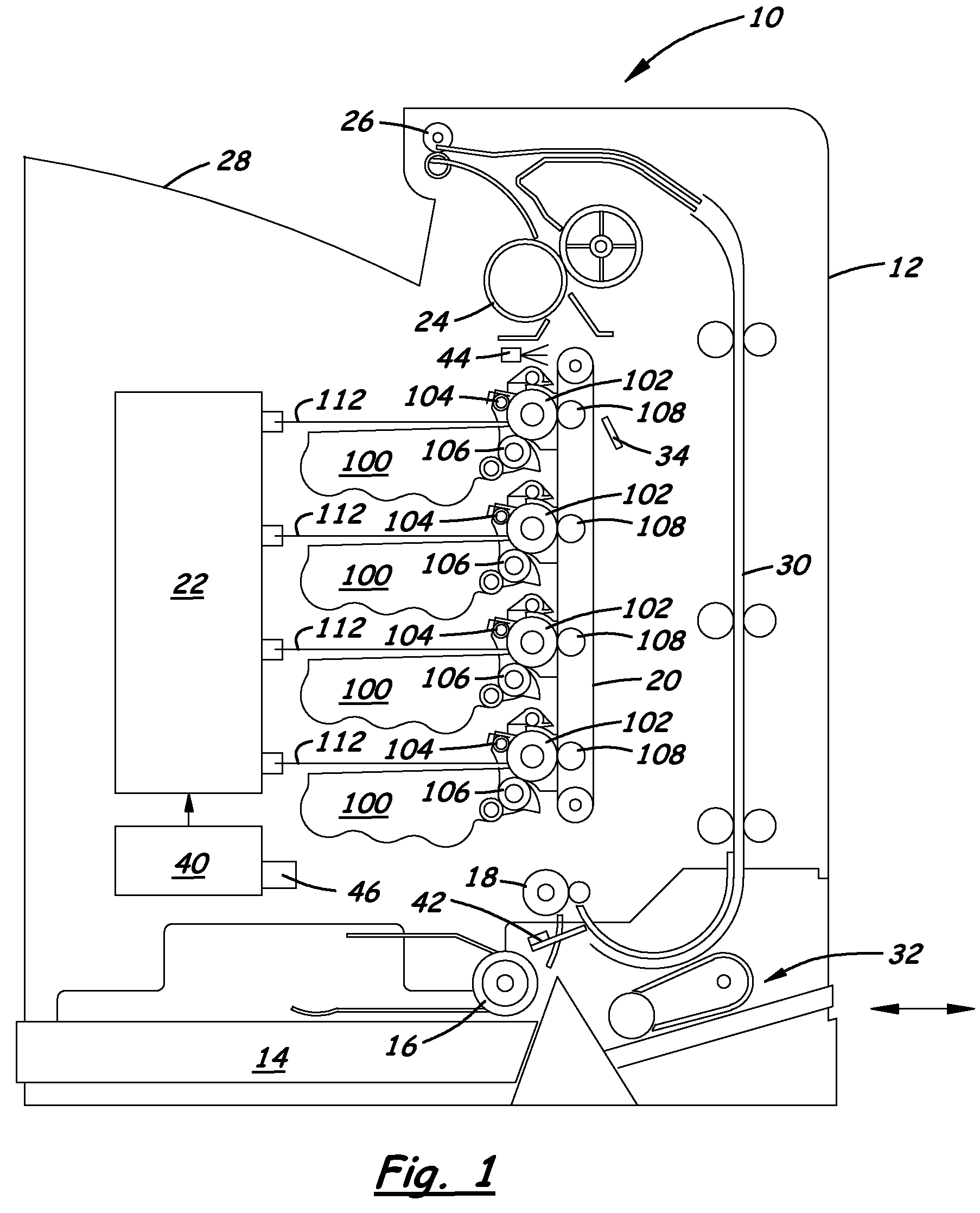
[0023]Referring now to FIG. 1, there is schematically illustrated an EP image forming device, generally designated 10, to which the system and method of the present invention are applicable. The exemplary image forming device 10, which is a laser printer, includes a main body 12, at least one media tray 14, a pick mechanism 16, a registration roller 18, a media transport belt 20, a laser printhead 22, a plurality of image forming stations 100, a fuser roller 24, exit rollers 26, an output tray 28, a dupl...


PUM


Abstract

A system for adjusting selected operating parameters of an image forming device to improve color registration based on selected environmental conditions includes a first image forming station to print a first registration mark on a substrate, a second image forming station to at least partially erase the first registration mark to form a registration pattern in a reverse transfer process of the color registration, and a control mechanism to adjust voltage biases of charge and developer rolls of the second image forming station based on wet-bulb temperature values determined from measured dry-bulb temperature and relative humidity values and stored in a lookup table so as to maintain a predetermined potential difference between charged and uncharged areas of a PC drum of the second image forming station that avoids Paschen breakdown and the development of toner at charged areas of the PC drum during the reverse transfer process of the color registration.

Description

CROSS REFERENCES TO RELATED APPLICATIONS[0001]None.BACKGROUND[0002]1. Field of the Invention[0003]The present invention relates generally to an electrophotographic (EP) image forming device and, more particularly, to a system and method for adjusting operating parameters, namely, bias voltages of charge and developer rolls, of the image forming device based on selected environmental conditions, namely, wet-bulb temperature values derived from dry-bulb temperature sensor and relative humidity sensor readings, to improve color registration.[0004]2. Description of the Related Art[0005]An EP image forming device, such as a single pass EP printer, typically employs four image forming stations, each one responsible for printing one of four primary colors, typically cyan, magenta, yellow, and black. The individual images, known as separations, produced by each of the four image forming stations are combined to produce the final output image. In tandem print engines, the four image forming ...

Claims


Application Information

Patent Timeline
Patent Type & Authority Applications(United States)
IPC IPC(8): G03G15/00G03G15/02G03G15/08
CPCG03G15/0266G03G21/203G03G2215/0634G03G15/065
Inventor BOOTH, ROBERT REEDBROCKMAN, RYAN DAVIDEMBRY, KERRY LELANDETTER, PAUL WESLEYMARIN, CLAUDIA ALEXANDRA
Owner LEXMARK INT INC
Why Eureka
Try Eureka