Vehicle load control device

a load control and vehicle technology, applied in secondary cell servicing/maintenance, safety/protection circuits, instruments, etc., can solve the problems of increasing the concern of the state of the battery, so as to prevent the power consumption of the detection operation itself from increasing, improve the consumption amount of the battery, and improve the probability.

Active Publication Date: 2010-04-01
HONDA MOTOR CO LTD
View PDF1 Cites 59 Cited by
  • Summary
  • Abstract
  • Description
  • Claims
  • Application Information

AI Technical Summary

Benefits of technology

[0013]According to the vehicle load control device of the present invention, since the time interval for detecting the consumption state of the battery is changed depending on the consumption amount (consumption level) of the battery when the ignition switch is off, it is possible to detect the consumption state of the battery while ensuring the desired detection accuracy with the necessary minimum detection interval, which is depending on the state of the working conditions of the electrical load when the ignition switch is off. So that it is possible to prevent the power consumption of the detection operation itself from increasing.
[0014]Furthermore, according to the vehicle load control device of the present invention, in the case where the consumption amount of the battery after the ignition switch is turned off is greater than or equal to a predetermined value, it is determined that there is a high probability that the operator has forgotten to turn off the power supply to the first electrical load, so the power supply to the first electrical load is cut off by the first control. In this manner, there is a high probability that the consumption amount of the battery can be improved with no need for direct detection of the electrical load in operation state, so that it is possible to reduce the consumption amount of the battery efficiently while preventing the cost from increasing.
[0015]Moreover, according to the vehicle load control device of the present invention, by cutting off the power supply to the first electrical load in response to the duration of the first control, it is possible to prevent power from being consumed unnecessarily in a state in which there is a high probability that the operator has forgotten to turn off the power supply to the first electrical load. As a result, compared with the case where the power supply to the electrical load is cut off routinely depending only on the consumption state of the battery, for example, it is possible to prevent the battery from deteriorating even more.
[0016]Furthermore, according to the vehicle load control device of the present invention, in the case where the consumption amount of the battery is less than or equal to a predetermined value, and is improved by the first control, by performing the second control it is possible to determine whether or not to continue to supply power to the electrical load that requires power consumption which is a relatively low consumption amount. As a result, detailed controls are possible, such as cutting off the power supply to an electrical load such as an interior light that is lighting-up because the operator forgot to turn it off for example, maintaining the power supply to the electrical load of a backup system, or the like, so that it is possible to improve the convenience while controlling the increase in the power consumption of the battery.
[0017]Moreover, in the case where the consumption amount of the battery does not drop to a predetermined value or below, and is not improved even if the first control is performed, it is determined that there is a high probability that the second electrical load is in an abnormal state, so it is possible to prevent unnecessary power consumption by cutting off the power supply to the second electrical load.
[0018]Furthermore, according to the vehicle load control device of the present invention, it is possible to detect the consumption state of the battery at appropriate time intervals as required depending on the consumption state of the battery, so that it is possible to prevent excess power from being consumed in order to detect the consumption state of the battery.

Problems solved by technology

Thereby the power consumption of the detection operation itself is increased.
Therefore, there is concern about the state of the battery deteriorating.

Method used


Image

  • Vehicle load control device
  • Vehicle load control device
  • Vehicle load control device

Examples


Embodiment Construction

[0025]Hereunder are a description of a vehicle load control device and a display control method of a vehicle according to an embodiment of the present invention, with reference to the appended drawings.

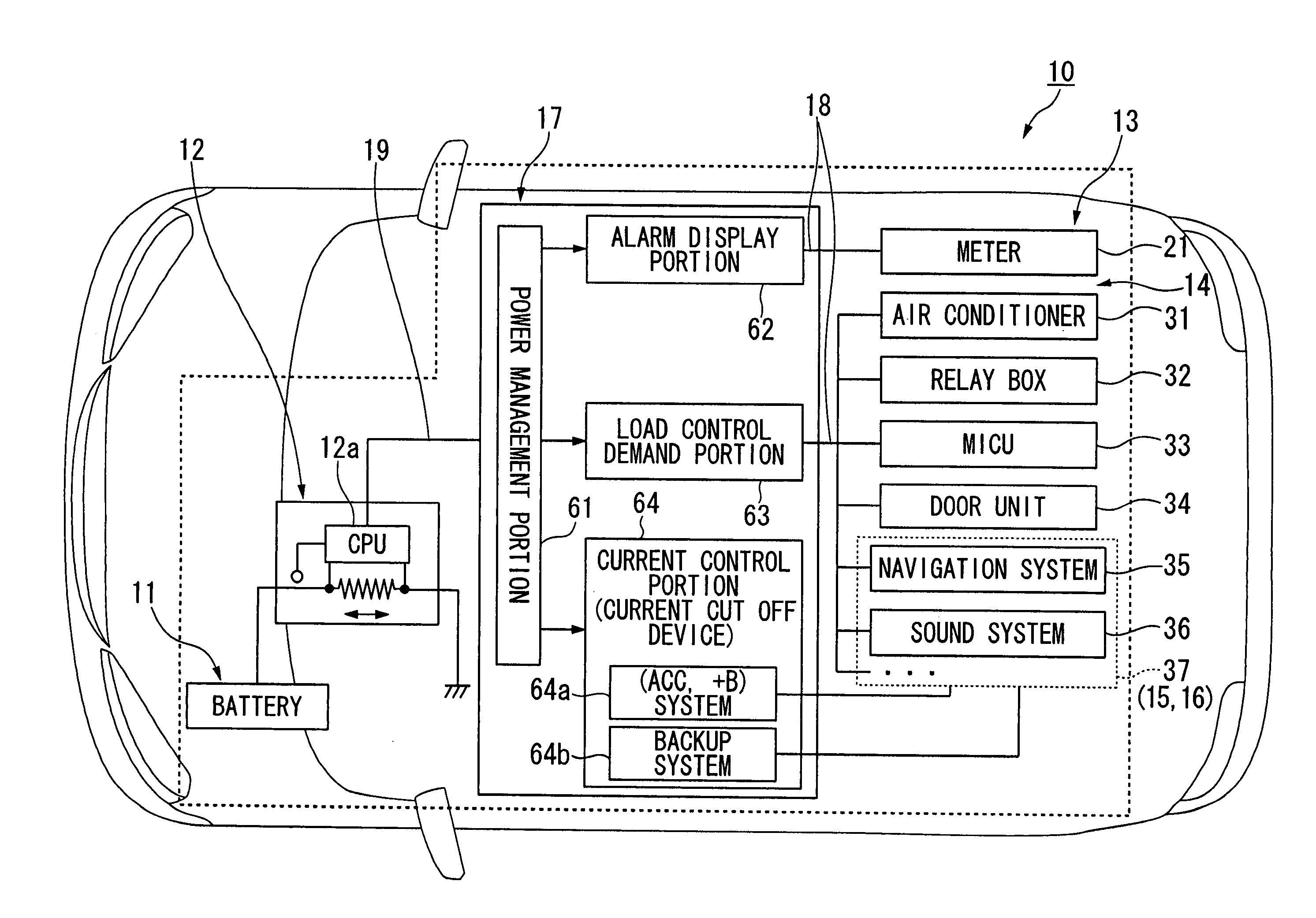
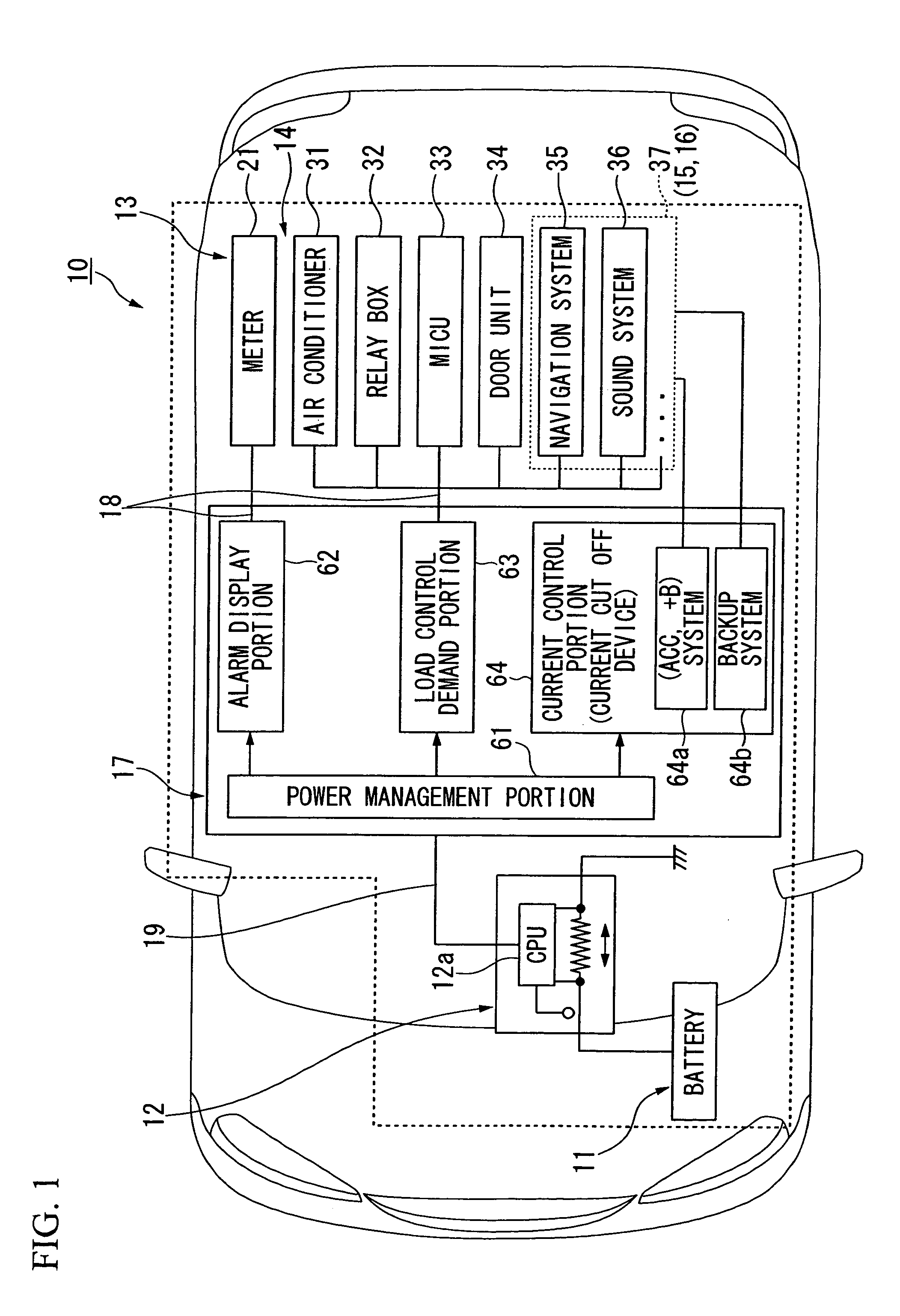
[0026]As shown in FIG. 1, for example, a vehicle load control device 10 according to the present embodiment includes a battery 11, a battery sensor 12, an alarm display device 13, an ignition system (IG system) electrical load 14, a first electrical load 15, a second electrical load 16, and a power management unit 17.

[0027]The battery 11 is a 12 volt battery consisting of a lead battery, for example.

[0028]The battery sensor 12 includes sensors for detects each of current, voltage, and temperature of the battery 11, and a CPU (central processing unit) 12a for performing a range of calculation processing such as calculating the battery residual capacity (for example state of charge SOC which is a parameter of the state of charge of the battery 11). The battery sensor 12 detects the batt...


PUM


Abstract

A vehicle load control device comprises a battery that supplies power to an electrical load of the vehicle; a battery sensor that detects a consumption state of the battery; and a control unit that cuts off power supply to the electrical load when the consumption state of the battery reaches a predetermined state. The control unit detects a consumption state of the battery at a relatively short first time interval, in a case where a consumption amount of the battery after the engine stops is greater than or equal to a predetermined value, and detects a consumption state of the battery at a relatively long second time interval, in a case where the consumption amount of the battery after the engine stops is less than a predetermined value, and cuts off power supply to the electrical load depending on the consumption state of the battery detected by the battery sensor.

Description

BACKGROUND OF THE INVENTION[0001]1. Field of the Invention[0002]The present invention relates to a vehicle load control device.[0003]The present invention claims priority on Japanese Patent Application No. 2008-247051, filed on Sep. 26, 2008, the contents of which are incorporated herein by reference.[0004]2. Description of Related Art[0005]Heretofore, a control device is known in which, for example, after every time that a vehicle is parked the state of the power consumption of its battery is detected, and based on the detection result, the power source is cut off before a preset power source cut off period (for example, Japanese Unexamined Patent Application, First Publication No. 2003-63330).[0006]Incidentally, in a control device according to an example of the above-described conventional technique, the state of the power consumption of the battery is detected routinely regardless of, for example, the state of the power consumption of the battery, or the usage state of the elect...

Claims


Application Information

Patent Timeline
Patent Type & Authority Applications(United States)
IPC IPC(8): G06F7/00
CPCB60R16/033H02J7/0032H01M10/42G01R31/3606G01R31/382H02J2310/46Y02E60/10
Inventor ARAI, TAKASHIISHIDA, KENICHI
Owner HONDA MOTOR CO LTD
Why Eureka
Try Eureka