
Apparatus, method and program for controlling drag and drop operation and computer terminal

Inactive Publication Date: 2010-04-01
FUJIFILM CORP
View PDF7 Cites 130 Cited by
  • Summary
  • Abstract
  • Description
  • Claims
  • Application Information

AI Technical Summary

Benefits of technology

[0008]An object of the present invention is to provide an apparatus, a method and a program for improving operability of a drag and drop operation and a computer terminal.
[0021]A drag and drop control program of the present invention causes the computer to execute the method for controlling the drag and drop operation of the present invention.
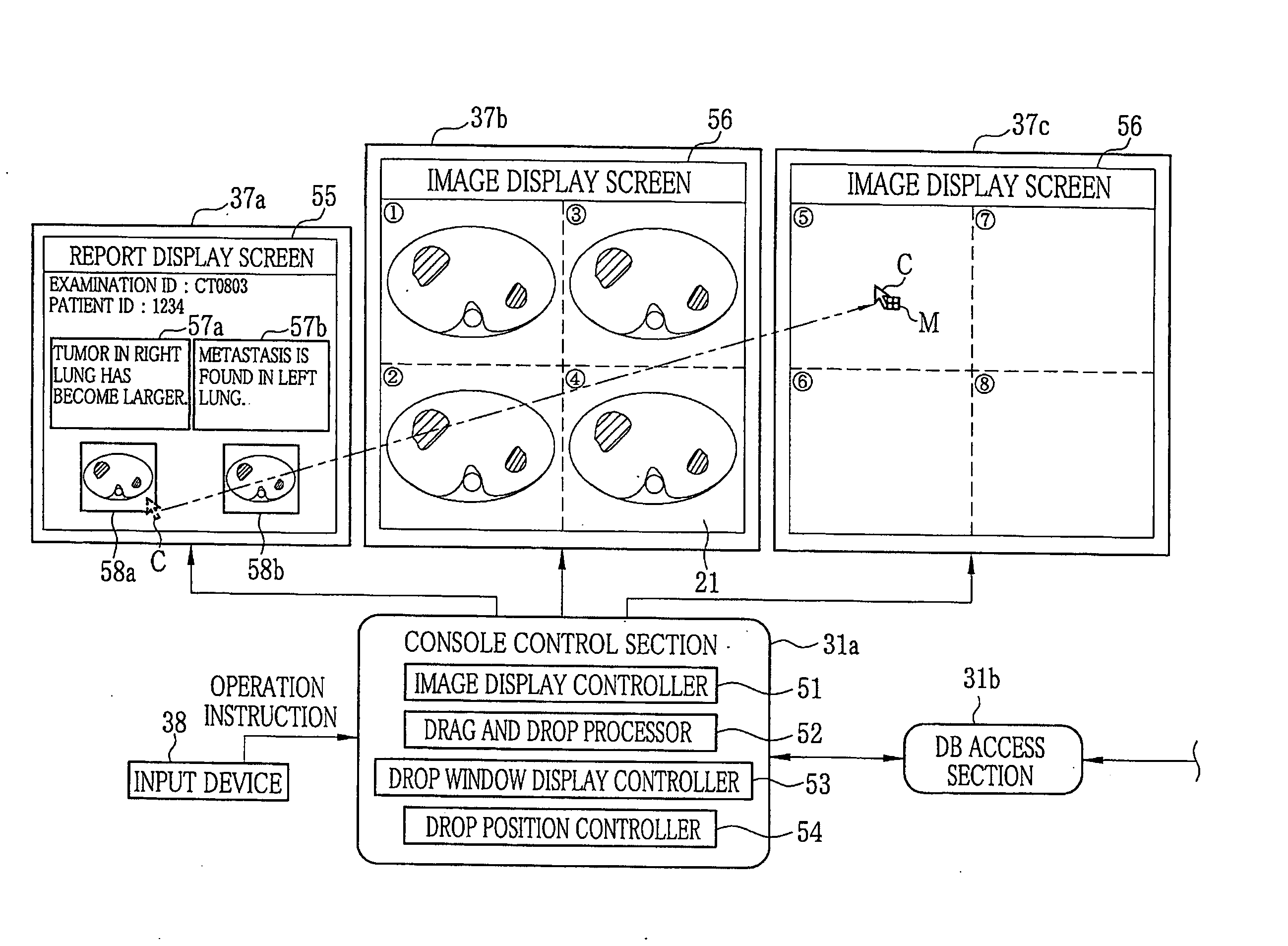
[0024]According to the present invention, the drop window that is the reduced image of the actual drop target area is displayed in a position closer to the object than the actual drop target area. When the object is dropped in the drop window, the object is dropped in a position inside the actual drop target area, corresponding to the drop position of the object in the drop window. Accordingly, the drag distance is reduced without complicating the operation, and thus the operability of the drag and drop operation is improved.

Problems solved by technology

As a result, operability is impaired, which likely to cause fatigue to a user.
However, it is not preferable to add operations to the drag and drop operation that requires the operation to select and move the object.
If an operation other than the cursor-moving operation is added for the purpose of reducing the mouse drag distance, it makes the drag and drop operation complicated and impairs operability.
Cursor moving methods disclosed in Japanese Patents No. 3566916 and 3646860 and U.S. Pat. No. 5,635,954 only intend to improve the operability of moving a cursor, but not the operability of the drag and drop operation.

Method used


Image

  • Apparatus, method and program for controlling drag and drop operation and computer terminal
  • Apparatus, method and program for controlling drag and drop operation and computer terminal
  • Apparatus, method and program for controlling drag and drop operation and computer terminal

Examples


Embodiment Construction

[0036]A medical information system, provided in a medical facility such as a hospital, supports creating interpretation reports (or simply referred to as reports) and viewing them by managing the created reports in a retrievable manner. The reports describe interpretation of examination images taken with medical modalities such as a CR (Computed Radiography) device, a CT (Computed Tomography) device and a MRI (Magnetic Resonance Imaging) device. The reports are created by, for example, radiologists who are specialized in diagnostic imaging. Hereinafter, a medical information system according to the present invention is described.

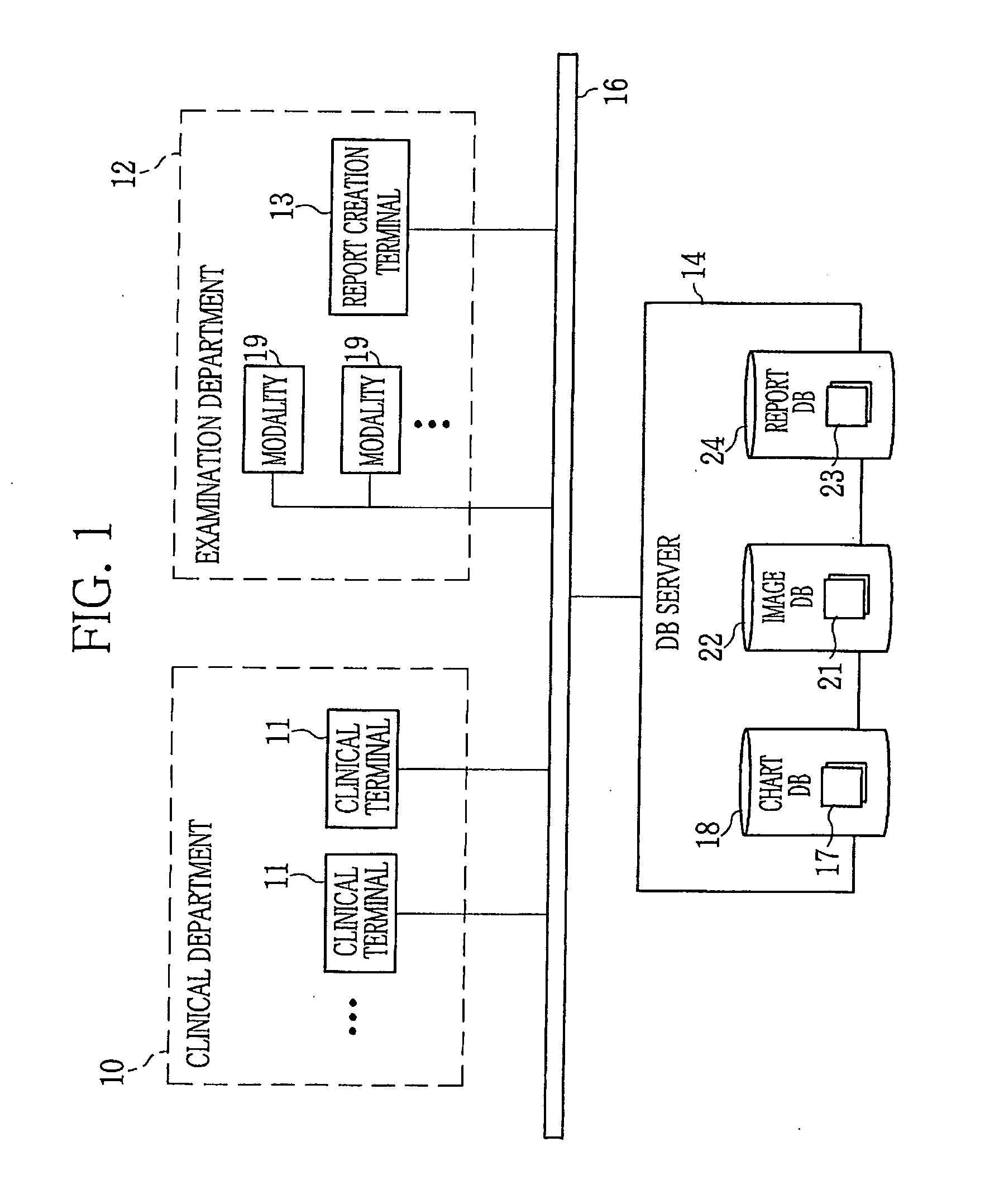
[0037]In FIG. 1, a medical information system is composed of a clinical terminal 11 installed in a clinical department 10, a report creation terminal 13 installed in a radiological examination department (hereinafter simply referred to as examination department) 12 and a database (DB) server 14. These are communicably connected via a network 16. The network ...


PUM


Abstract

Multiple displays are placed side by side. A key image to be drag-and-dropped is displayed on a first display. An actual drop target area into which the key image is to be dropped is displayed on the rest of the displays. The key image is held by placing a cursor thereon and pressing a right click button of a mouse. In response to this, a drop window that is a reduced image of the drop target area is displayed on the first display. The cursor is moved onto the drop window by operating the mouse with the right click button pressed. Releasing the right click button in a desired position in the drop window drops the key image. Based on a drop position in the drop window, the key image is dropped in a corresponding position in the actual drop target area.

Description

FIELD OF THE INVENTION[0001]The present invention relates to an apparatus, a method and a program for controlling a drag and drop operation to move or copy an object displayed on a screen and a computer terminal.BACKGROUND OF THE INVENTION[0002]Recently, various operating systems such as Windows (registered trademark) have a so-called multi-display function, that is, a function to control multiple displays using one computer. The multi-display function enables the computer to display a single image across two or more displays, or a different image on each of the displays. With the use of the multi-display function, a cursor that selects an object on a screen moves across the multiple displays in accordance with the operation of a pointing device such as a mouse.[0003]For example, in a medical information system, a multi-display terminal having at least two displays is used. On the displays are displayed separately an interpretation report of an examination image interpreted by a doc...

Claims


Application Information

Patent Timeline
IPC IPC(8): G06F3/048G06F3/14G06Q50/22G06Q50/24G16H10/60
CPCG06F3/0486G06F3/04886G06F19/321G06F19/3487G09G2370/24G06F3/1438G06F2203/04803G09G2340/0464G06F3/1431G16H15/00G16H30/20
Inventor TAKESHITA, MASANORI
Owner FUJIFILM CORP
Learn More