Motor control circuit and power window device

a technology of motor control circuit and power window device, which is applied in the direction of electric devices, program control, resistance welding apparatus, etc., can solve the problems of switch element cries and the window is opened

Active Publication Date: 2010-04-08
OMRON AUTOMOTIVE ELECTRONICS CO LTD
View PDF5 Cites 9 Cited by
  • Summary
  • Abstract
  • Description
  • Claims
  • Application Information

AI Technical Summary

Benefits of technology

[0018]Accordingly, one or more embodiments of the present invention can provide the motor control circuit and power window device to prevent the false determination that the catch is generated due to the chatter of the switch element.

Problems solved by technology

However, in the power window device disclosed in WO 00 / 37761, because the switch element is interlocked with the manipulation switch that is turned on and off by the manipulation of the manipulation knob, sometimes the switch element chatters due to a mechanical vibration in manipulating the manipulation knob.
Therefore, because the rotation (reverse rotation) of the motor is tentatively stopped, a false determination that the catch is generated is made, and the motor is switched to the normal rotation even if the window closing manipulation is performed, which causes a problem in that the window is opened.

Method used


Image

  • Motor control circuit and power window device
  • Motor control circuit and power window device
  • Motor control circuit and power window device

Examples


Embodiment Construction

[0034]Hereinafter, a preferred embodiment of the present invention will be described with reference to the drawings. The case in which the invention is applied to a power window device provided in a vehicle driving seat is described in the following embodiment.

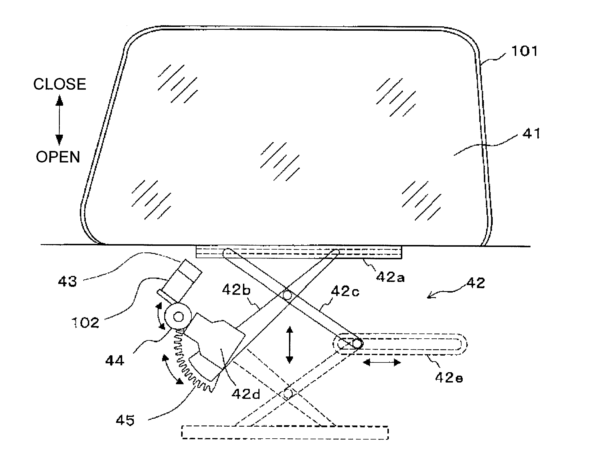
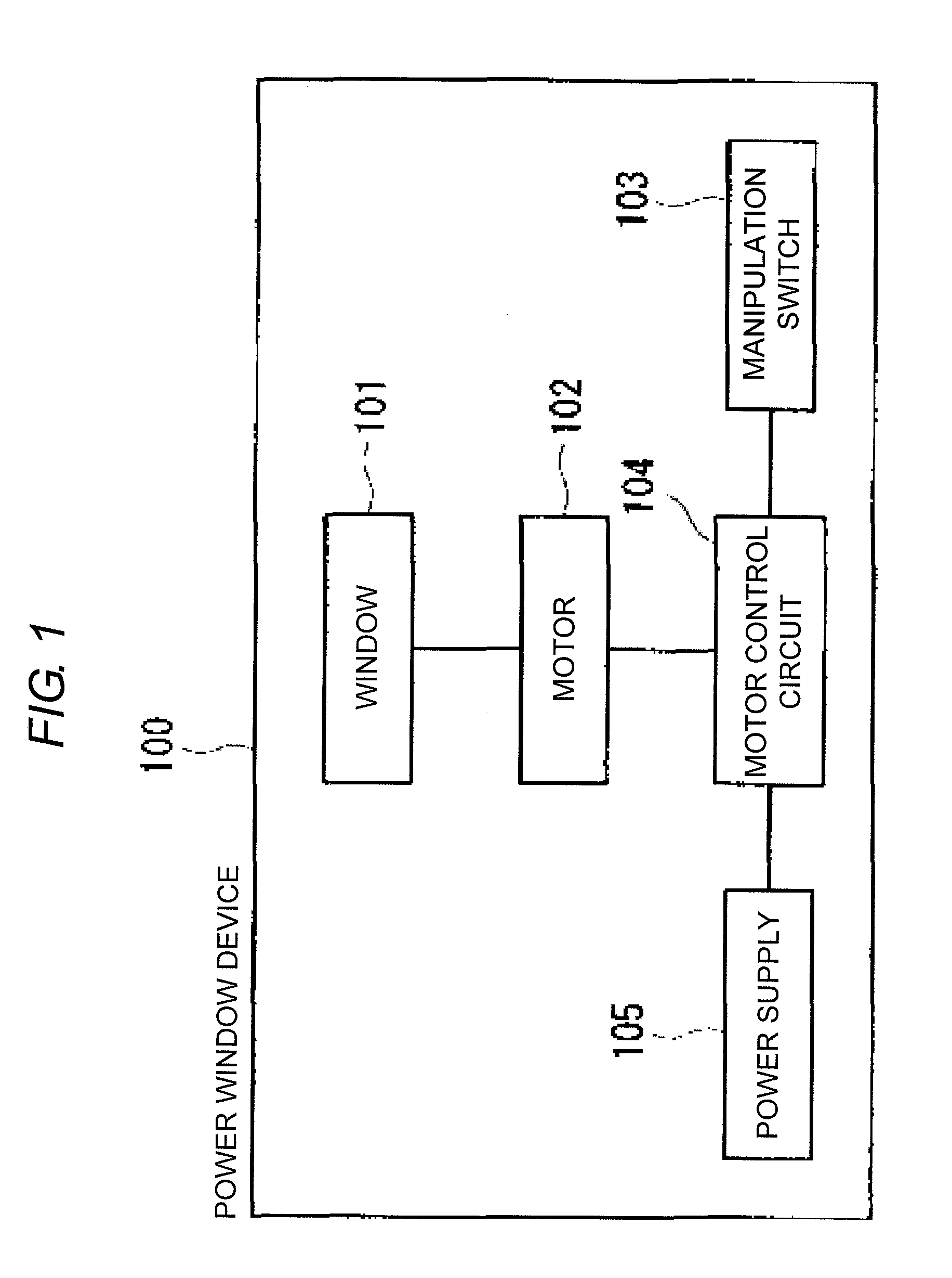
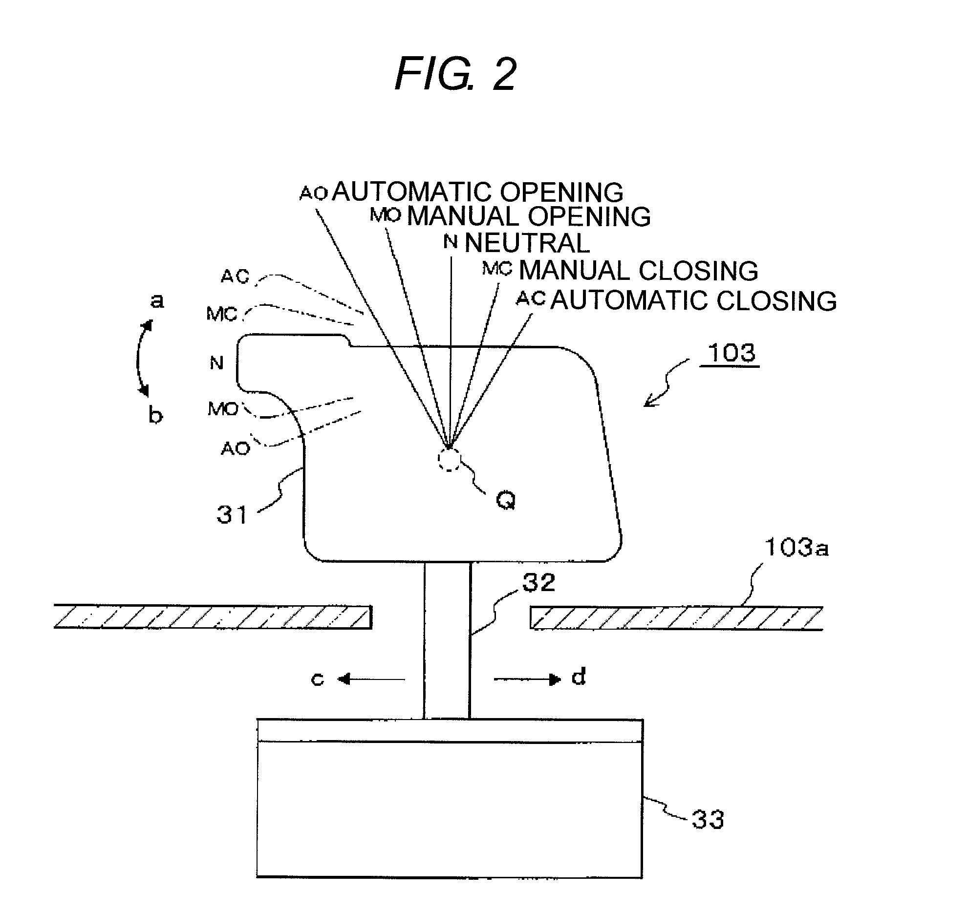
[0035]FIG. 1 is a block diagram illustrating a configuration of a power window device according to an embodiment of the invention. Referring to FIG. 1, a power window device 100 of the embodiment includes a driving-seat window 101, a motor 102 that opens and closes the window 101, a manipulation switch 103 that is used when a driver manipulates the window 101, a motor control circuit 104 that controls the motor 102, and a power supply 105 that supplies an electric power to the motor 102.

[0036]The motor 102 drives the window 101 in an opened direction when driven in a normal rotation direction, and the motor 102 drives the window 101 in a closed direction when driven in a reverse rotation direction.

[0037]FIGS. 2 and 3 are schem...


PUM

PropertyMeasurementUnit
currentaaaaaaaaaa
currentsaaaaaaaaaa
electric poweraaaaaaaaaa

Abstract

A motor control circuit includes a manipulation unit, a control unit that drives a motor in a normal rotation direction or a reverse rotation direction, a catch detecting unit that detects a foreign substance caught in the opening and closing body, a first relay circuit that connects one of terminals of the motor to a power supply when the motor is driven in the normal rotation direction, a second relay circuit that connects the other terminal of the motor to the power supply when the motor is driven in the reverse rotation direction, a switch element that cuts off connection to the power supply when the normal rotation command is fed into the control unit from the manipulation unit, a detection circuit, and a feed circuit.

Description

BACKGROUND OF THE INVENTION[0001]1. Technical Field[0002]The present invention relates to a motor control circuit and a power window device provided therewith.[0003]2. Related Art[0004]Conventionally, there are well known various power window devices including a window, a motor that opens and closes the window, and a motor control circuit that controls the motor (for example, see Japanese Unexamined Patent Publication Nos. 2007-224637 and 2008-106560). In such power window devices, a window opening operation is performed by a normal rotation of the motor, and a window closing operation is performed by a reverse rotation of the motor.[0005]In the power window device disclosed in Japanese Unexamined Patent Publication No. 2007-224637, a manipulation knob is provided so as to be switched to positions of “automatic closing AC”, “manual closing MC”, “neutral N”, “manual opening MO”, and “automatic opening AO”. In the power window device, once the manipulation knob is switched to the posi...

Claims


Application Information

Patent Timeline
Patent Type & Authority Applications(United States)
IPC IPC(8): E05F15/18H02H7/093E05F15/60
CPCE05Y2900/55G05B19/4061G05B2219/45242G05B2219/49162H02H1/04E05F15/695E05Y2400/44E05Y2800/428E05Y2900/50E05F15/40E05F15/41H02H7/0851
Inventor KIGOSHI, KATSUNORI
Owner OMRON AUTOMOTIVE ELECTRONICS CO LTD
Why Eureka
Try Eureka