Method and apparatus for the utilization of waste heat from gaseous heat sources carrying substantial quantities of dust

a waste heat and gaseous heat technology, which is applied in the direction of indirect heat exchangers, lighting and heating apparatus, machines/engines, etc., can solve the problems of inability to install effective filters to separate the dust directly from the gaseous stream, and the use of this heat sour

Active Publication Date: 2010-04-08
KALINA POWER LTD
View PDF99 Cites 33 Cited by
  • Summary
  • Abstract
  • Description
  • Claims
  • Application Information

AI Technical Summary

Problems solved by technology

However, a significant obstacle to the utilization of this heat source is the fact the gas and air carries a substantial quantity of abrasive dust.
Because these sources usually have very small gage pressure (i.e., pressure above atmospheric pressure) it is impossible to install effective filters to separate this dust directly from the gaseous stream.
If these heat source are not cleaned of dust, the dust will cause substantial erosion of the surfaces of heat exchangers and diminishes the efficiency of heat transfer as a result of the dust being deposited as sedimentation on the heat transfer surfaces.

Method used


Image

  • Method and apparatus for the utilization of waste heat from gaseous heat sources carrying substantial quantities of dust
  • Method and apparatus for the utilization of waste heat from gaseous heat sources carrying substantial quantities of dust
  • Method and apparatus for the utilization of waste heat from gaseous heat sources carrying substantial quantities of dust

Examples


Embodiment Construction

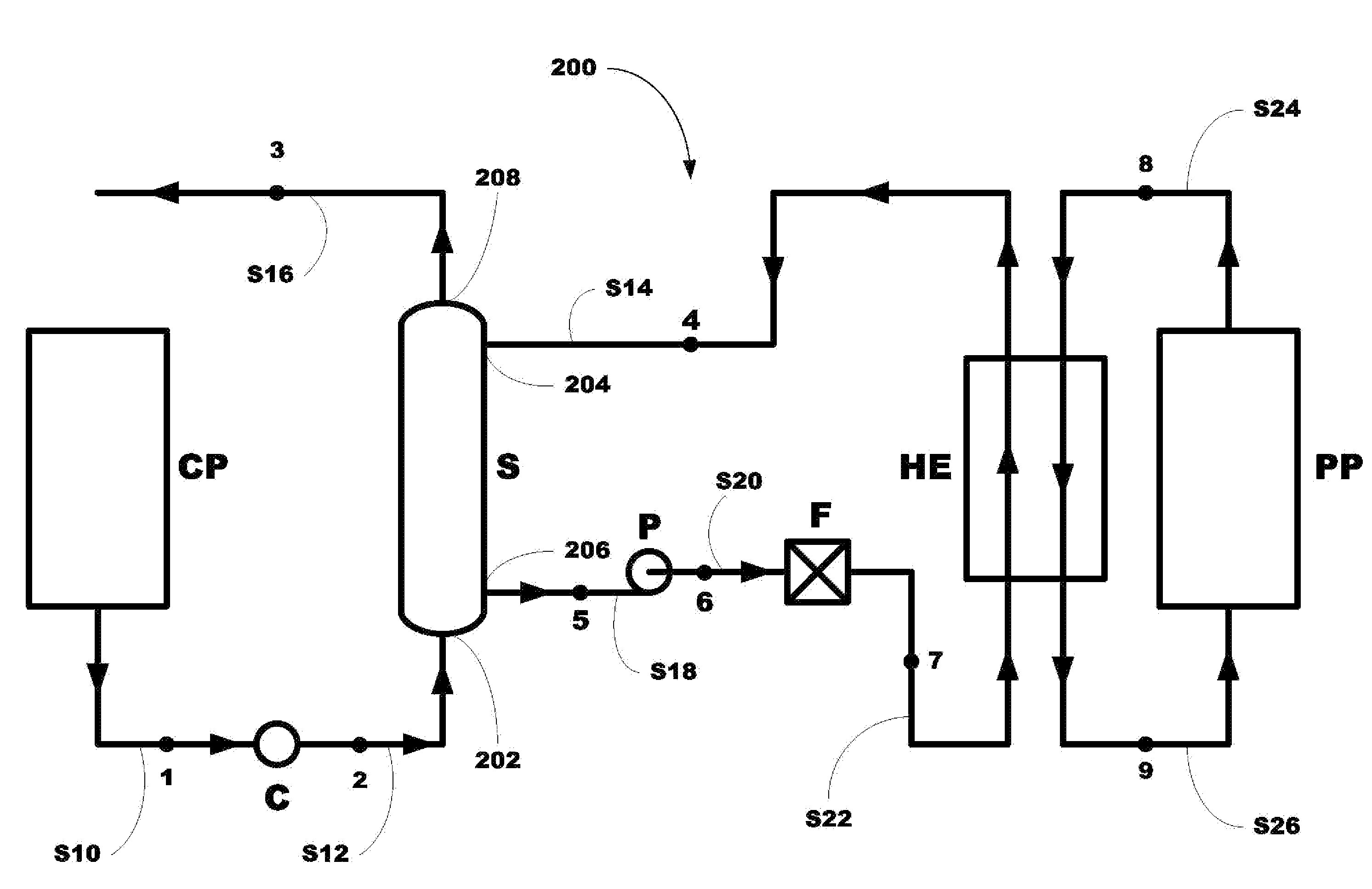
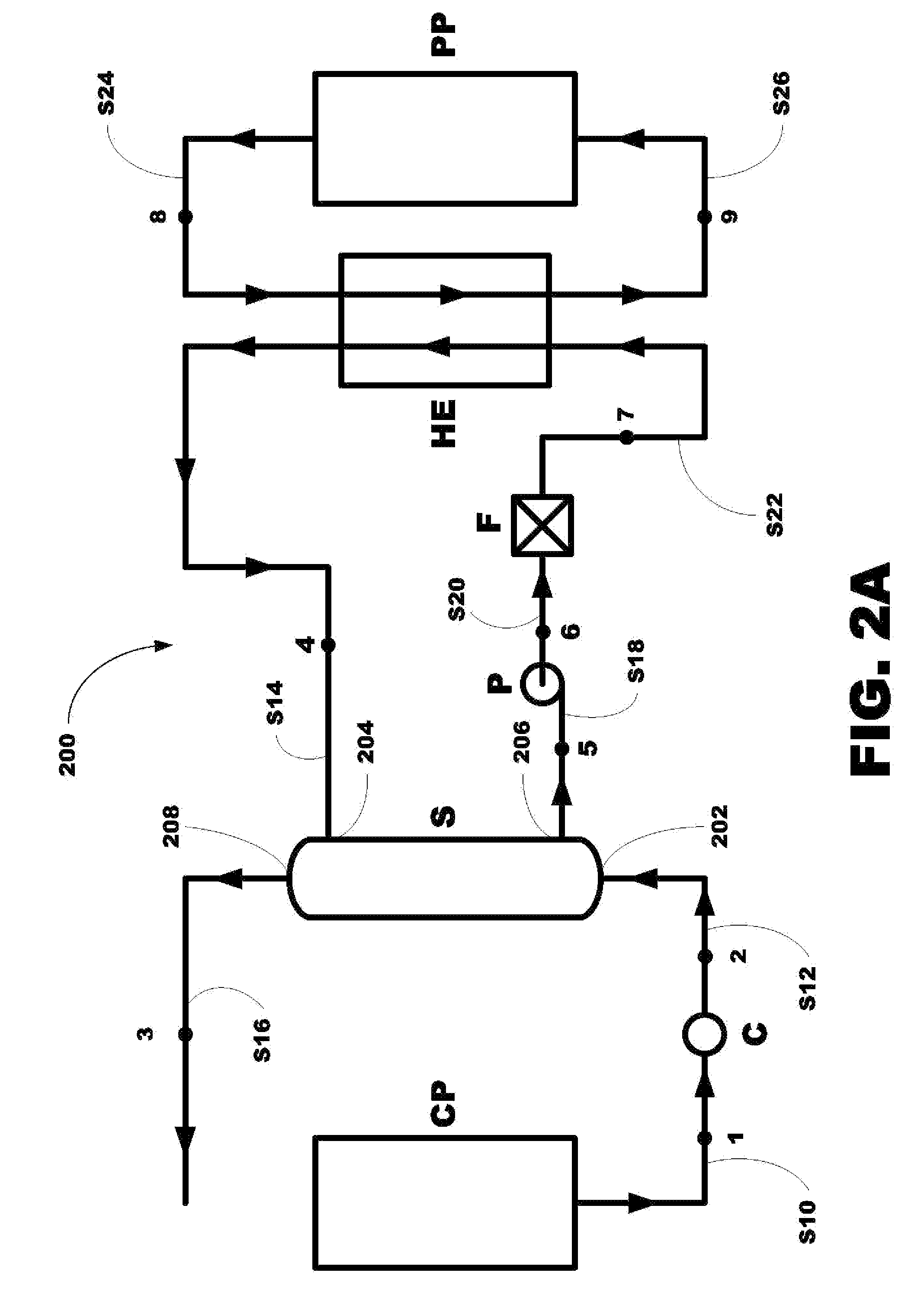
[0025]The inventor has constructed a system and method for transferring heat from a hot flue gas stream produced by a cement plant to a high temperature heat transfer fluid stream and to a working fluid stream without exposing the equipment or most of the equipment to the erosive propensity of the hot flue gas cement plant stream, with includes large particles and dust.

[0026]The subject of the proposed invention is a process and apparatus for separating dust from gaseous waste heat sources and providing effective heat transfer to the working fluid of a power cycle that utilizes such waste heat.

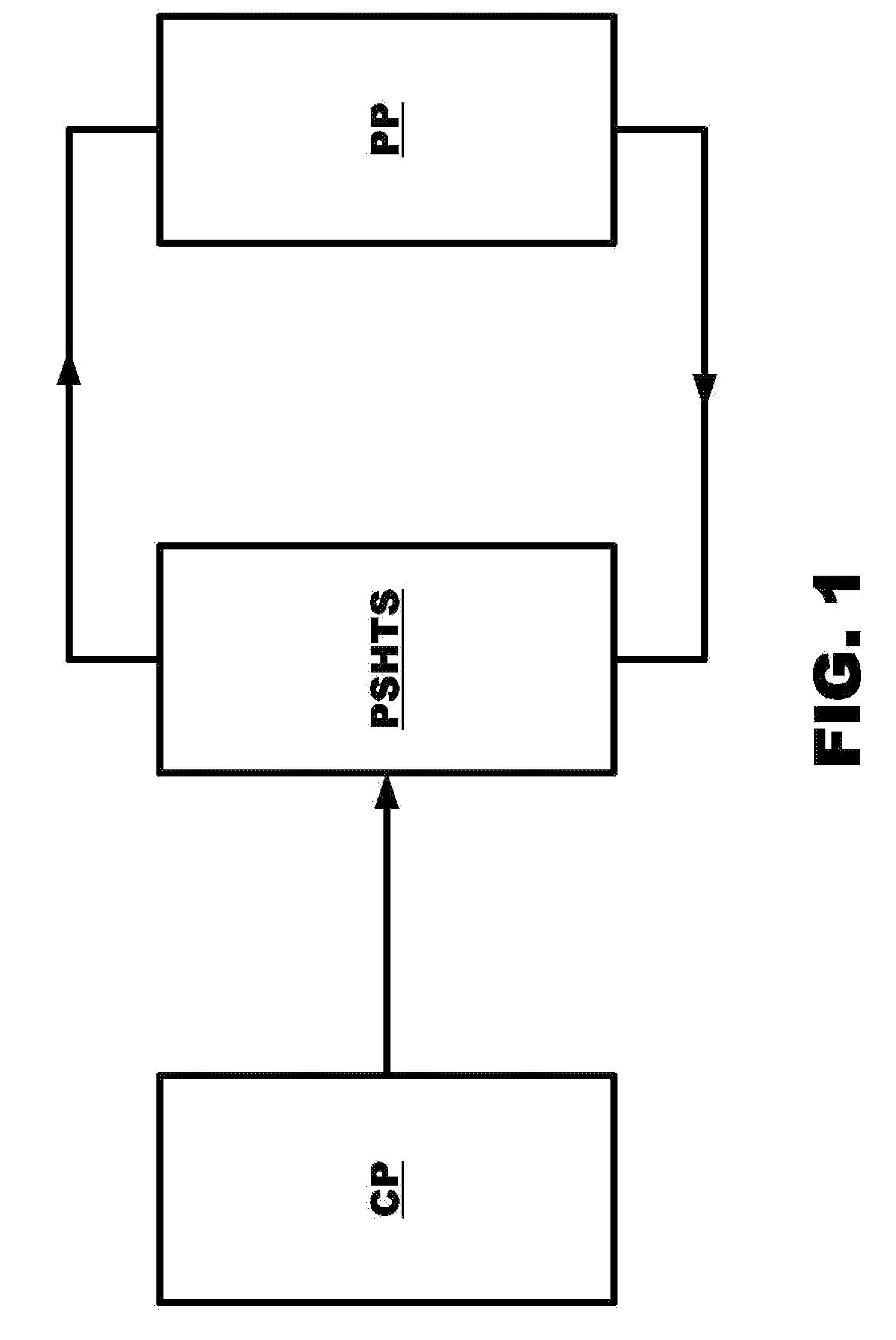
[0027]Referring now to FIG. 1, an embodiment of a system of this invention, generally 100, is shown to include a cement plant CP, a particulate separation and heat transfer system PSHT adapted to receive a hot gas stream S1 from the cement plant CP including large particles and dust and a power plant PP adapted to send a working fluid stream S2 through the PSHT to form a vaporized working flui...


PUM

PropertyMeasurementUnit
temperatureaaaaaaaaaa
pressureaaaaaaaaaa
packing structureaaaaaaaaaa

Abstract

An apparatus, system and method for transferring heat from a hot flue gas stream from a cement plant including large particles and dust to a working fluid of a power plant via a high temperature heat transfer fluid without exposing all or most of the equipment to the erosive force of the particles and dust is disclosed where the apparatus includes a cement plant, a particle separation and heat transfer system and a power plant

Description

BACKGROUND OF THE INVENTION[0001]1. Field of the Invention[0002]The present invention relates to an apparatus, system and method for transferring heat from a hot flue gas stream from a cement plant including large particles and dust to a working fluid of a power plant via a high temperature heat transfer fluid without exposing all or most of the equipment to the erosive force of the particles and dust.[0003]More particularly, the present invention relates to an apparatus, system and method for transferring heat from a hot flue gas stream from a cement plant including large particles and dust to a working fluid of a power plant via a high temperature heat transfer fluid without exposing all or most of the equipment to the erosive force of the particles and dust, where the apparatus includes a cement plant, a particle separation and heat transfer system and a power plant.[0004]2. Description of the Related Art[0005]A substantial source of waste heat available for utilization in power ...

Claims


Application Information

Patent Timeline
Patent Type & Authority Applications(United States)
IPC IPC(8): F02C3/00
CPCC04B7/36C04B7/475F01K13/00F28D21/0014F05C2253/12F28D9/04F28D21/001F05B2230/31Y02P40/121
Inventor KALINA, ALEXANDER I.
Owner KALINA POWER LTD
Why Eureka
Try Eureka