Intake system for vehicle internal combustion engine
- Summary
- Abstract
- Description
- Claims
- Application Information
AI Technical Summary
Benefits of technology
Problems solved by technology
Method used
Image

Examples
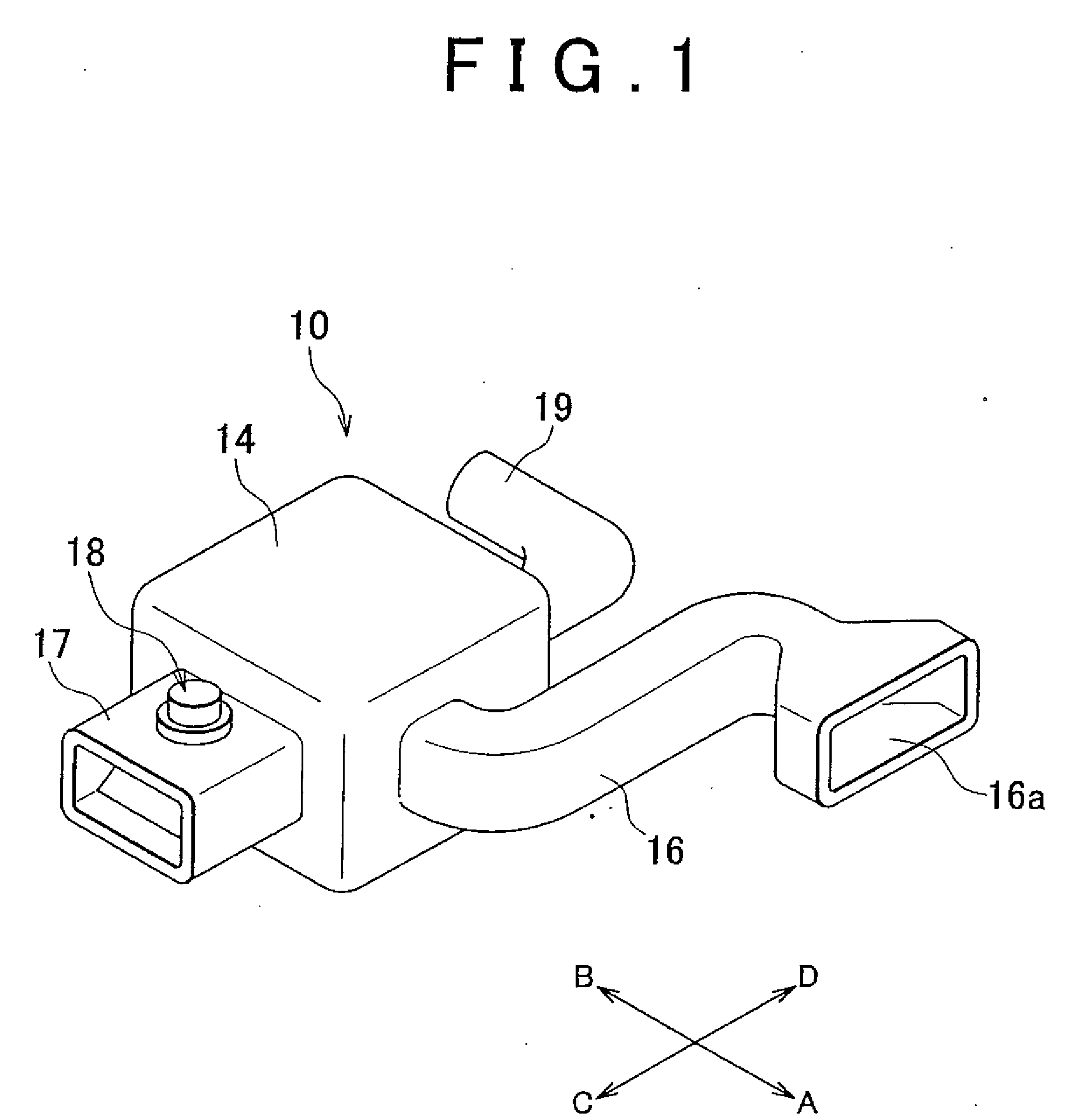
first embodiment
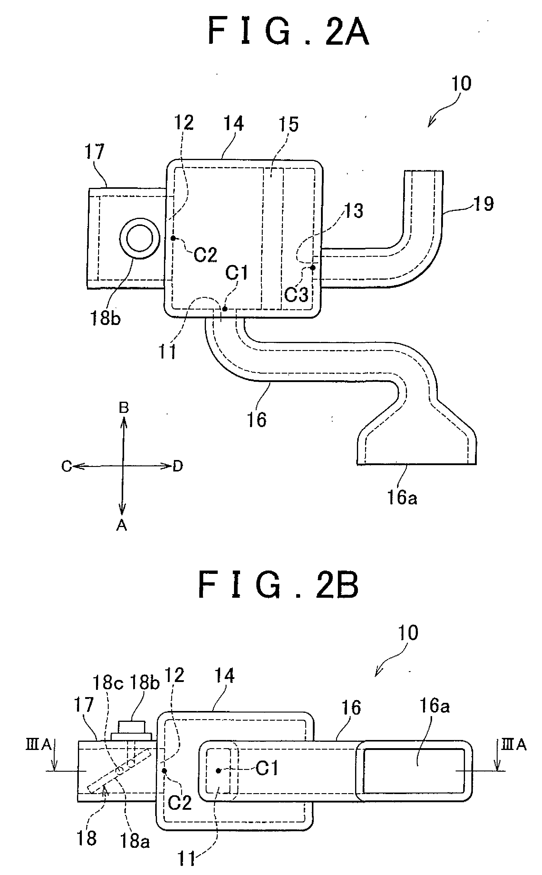
[0054]As described above, when the engine operates at a high-speed high-load region and the on-off valve 18a is opened, a sufficient amount of air is inhaled through the second air intake opening 12 and the airflow from the first air intake opening 11 into the air cleaner box 14 is facilitated by the flow of the air inhaled from the second air intake opening 12 to the communication opening 13. Accordingly, even if the engine operates at a high-speed high-load region, a sufficient amount of air is inhaled from the second air intake opening 12 and a greater amount of low temperature air is inhaled from the first air intake opening 11, as compared with the conventional system. Thus, good engine performance can be obtained, when the engine operates at a high-speed high-load region.
[0055]Further, according to the first embodiment, the distance from the center of the first air intake opening 11 to the center of the second air intake opening 12 is set smaller than the distance from the ce...
second embodiment
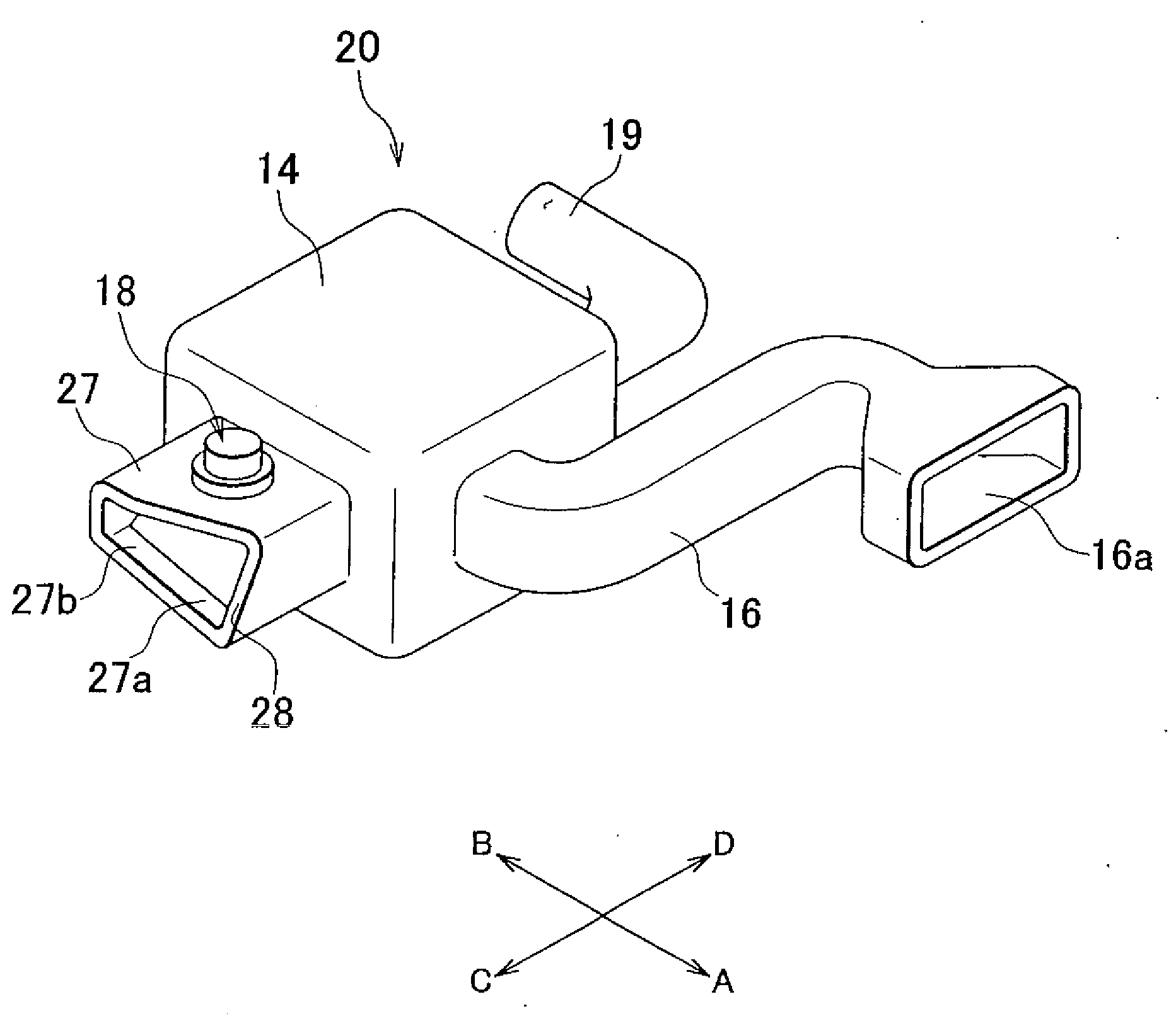
[0060]FIG. 5 through FIG. 7D show an intake system 20 for a vehicle internal combustion engine according to the present invention.
[0061]The second embodiment is different from the first embodiment in the respect that the shape of a second air intake opening and second air intake duct in the second embodiment is different from the shape of the second air intake opening 12 and second air intake duct 17 in the first embodiment. Therefore, the portions or components in FIG. 5 through FIG. 7D that are the same as or correspond to those in the intake system 10 for the vehicle internal combustion engine according to the first embodiment are explained using the same reference numerals shown in FIG. 1 to FIG. 3C. The portions different from those in the first embodiment are explained in detail below.
[0062]In the intake system 20 for the internal combustion engine of the second embodiment as shown in FIG. 5, the second air intake opening 22 has a wide width portion 22a and a narrow width port...
PUM
| Property | Measurement | Unit |
|---|---|---|
| Length | aaaaa | aaaaa |
| Width | aaaaa | aaaaa |
| Distance | aaaaa | aaaaa |
Abstract
Description
Claims
Application Information
 - R&D
- Intellectual Property
- Life Sciences
- Materials
- Tech Scout
- Unparalleled Data Quality
- Higher Quality Content
- 60% Fewer Hallucinations
Browse by: Latest US Patents, China's latest patents, Technical Efficacy Thesaurus, Application Domain, Technology Topic, Popular Technical Reports.
© 2025 PatSnap. All rights reserved.Legal|Privacy policy|Modern Slavery Act Transparency Statement|Sitemap|About US| Contact US: help@patsnap.com