

Mask device with blower
a mask and blower technology, applied in the direction of valve operating means/releasing devices, functional valve types, respirators, etc., can solve the problems of increasing the supply amount, and increasing the speed of the person wearing the mask devi
- Summary
- Abstract
- Description
- Claims
- Application Information
AI Technical Summary
Benefits of technology
Problems solved by technology
Method used
Image

Examples
first embodiment
[0028]A mask device with blower according to the present invention will be described with reference to FIGS. 1 to 6.
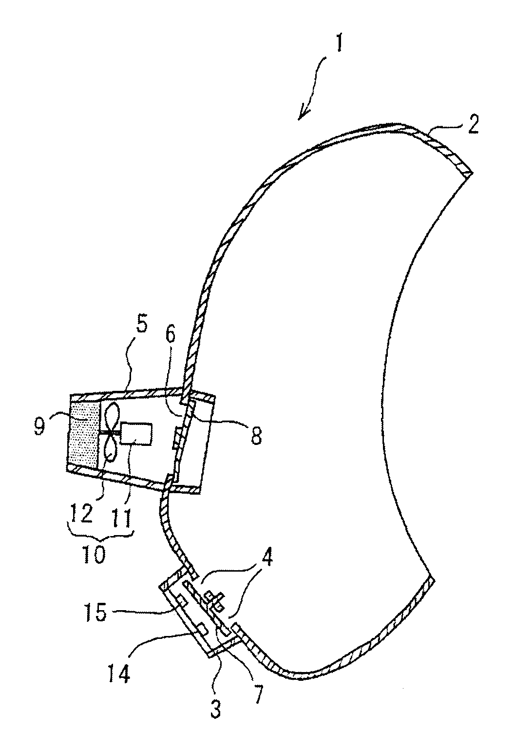
[0029]As shown in FIG. 1, a mask device with blower 1 includes an exhaust slot 4 and an inhalation slot 6 that are provided at an anterior portion of a face body 2. The exhaust slot 4 has an external surface that is covered with an exhaust valve cover 3, and the inhalation slot 6 has an external surface that is covered with a filtering material cover 5, similar to the exhaust slot.
[0030]The exhaust slot 4 is provided with an exhaust valve 7 that moves in an opening direction when a person who wears the mask device exhausts air and moves in a closing direction when the person inhales air, in accordance with breathing of the person. The inhalation slot 6 is provided with an inhalation valve 8 that is closed when the person exhausts air and opened when the person inhales air. In the filtering material cover 5, a filtering material 9 is disposed at its front end (end of th...
second embodiment
[0051]Next, a mask device with blower according to the present invention will be described with reference to FIGS. 7 and 8.
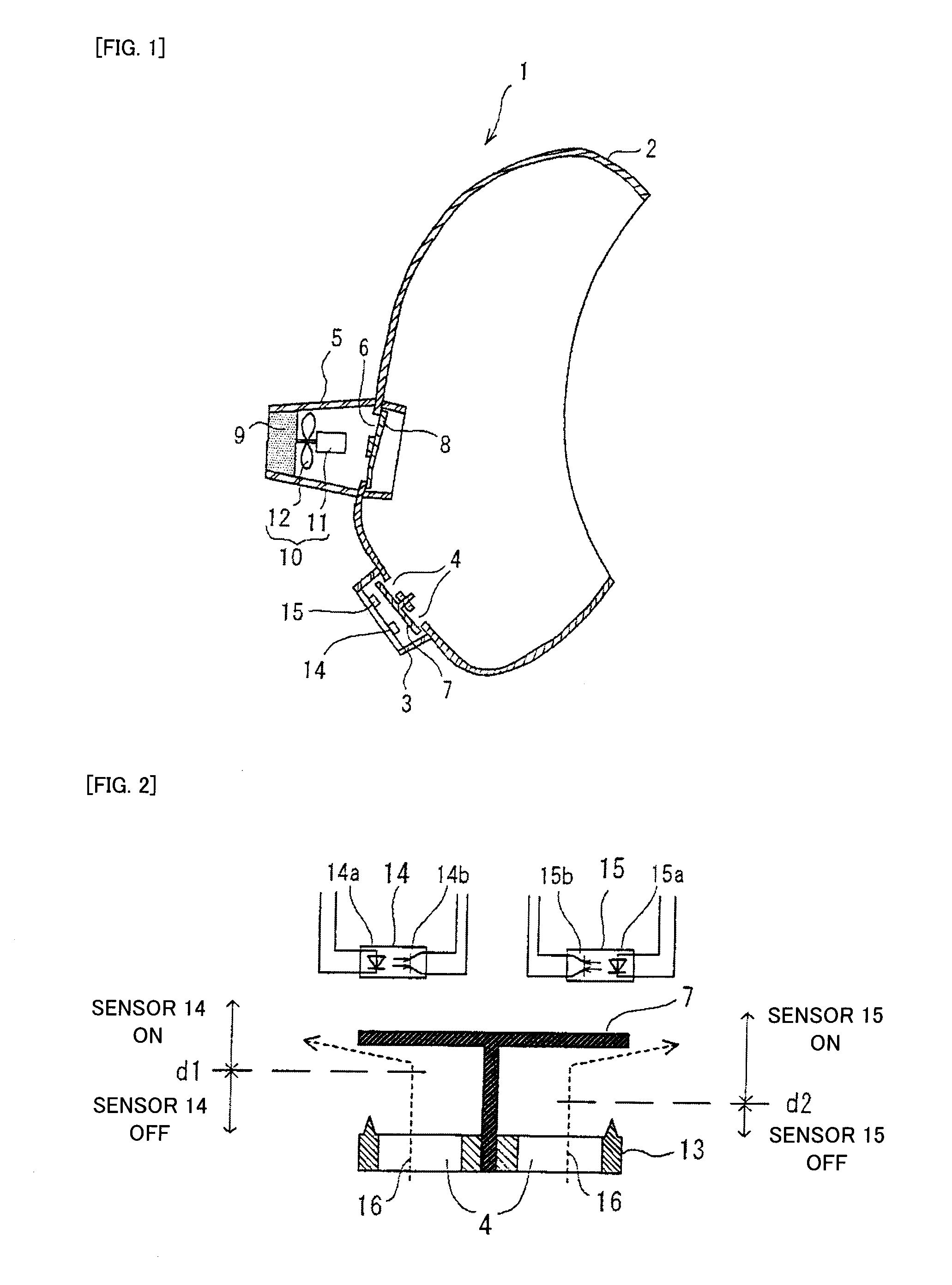
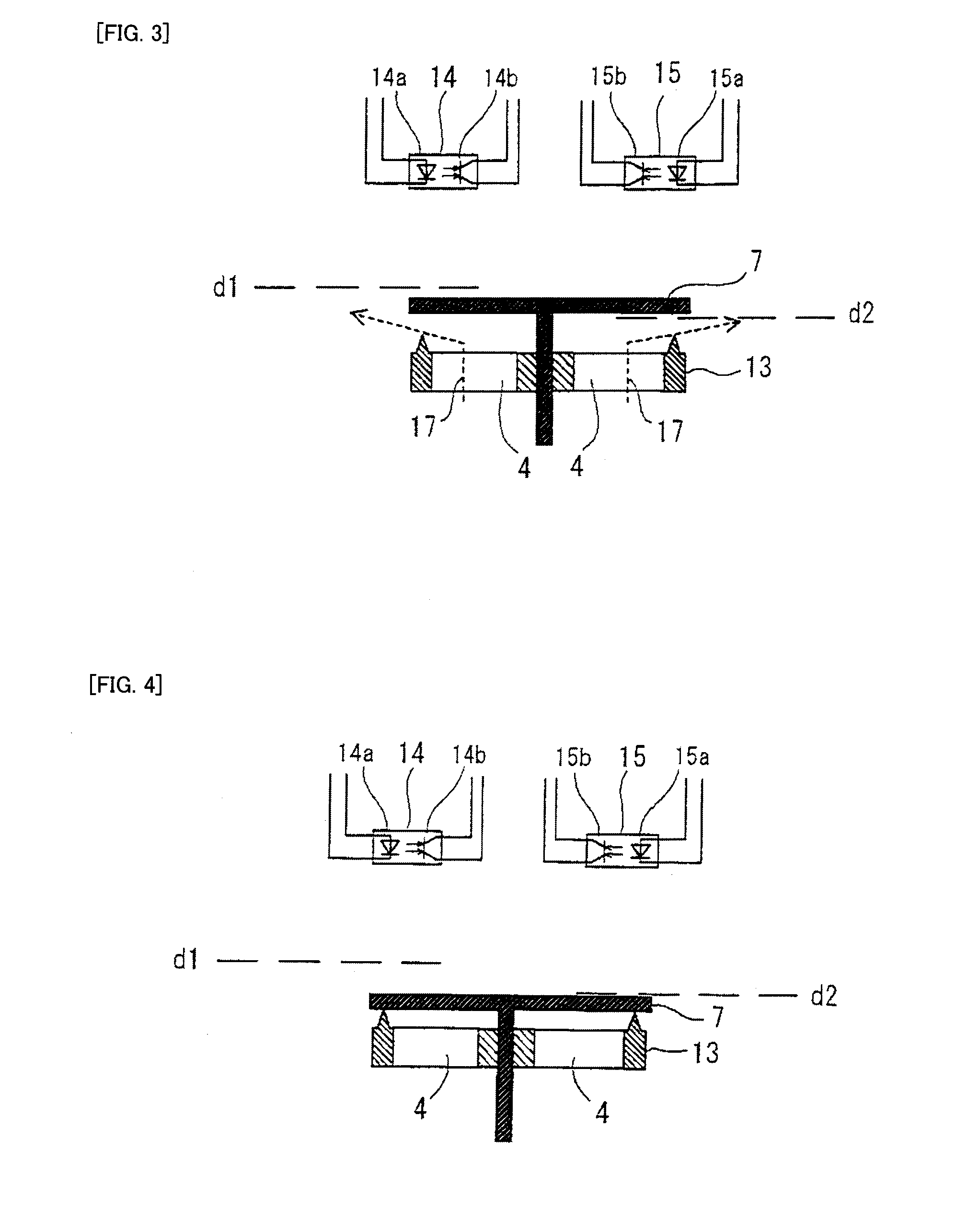
[0052]In the previously described first embodiment, the position detecting sensor 14 for blower control to follow breathing and the position detecting sensor 15 for warning to operate the warning device are individually provided with respect to the movement position of the exhaust valve 7. However, in the second embodiment, one position detecting sensor is provided with respect to the movement position of the exhaust valve 7 such that the position detecting sensor individually controls the blower 10 and the warning device (warning LED 20) in the control circuit.
[0053]FIG. 7 is a circuit diagram illustrating a portion of a control circuit that individually controls the blower 10 and the warning device. In this embodiment, similarly to the first embodiment, an LED (warning LED 20) is used as the warning device, and a position detecting sensor 14 (composed of a pho...
third embodiment
[0070]Next, a mask device with blower according to the present invention will be described with reference to FIG. 9.
[0071]FIG. 9 is a cross-sectional view illustrating the vicinity of an exhaust valve in a mask device with blower according to this embodiment (a state where a person who wears the mask device exhausts air). In the present invention, since the position (shape) of the exhaust valve 7 may be recognized in a non-contact state, the exhaust valve 30 to be detected is formed of a material (silicon rubber) in which a magnetic body is mixed. In addition, each of the sensor 28 for blower control and the sensor 29 for warning is composed of a magnetic resistance effect element (hereinafter, referred to as an MR sensor) that increases its resistance depending on the strength of the detected magnetism, instead of the photo interrupter. By this configuration, even though the position (shape) of the valve is recognized using the MR sensor, the same effect as that of the first and se...
PUM
 Abstract
Description
Claims
Application Information