
Mandibular advancement device with positive positioning hinge

a technology of mandibular advancement and hinge, which is applied in the field of devices for preventing sleeping problems, can solve the problems of high cost, time-consuming, and complicated operation, and achieve the effects of eliminating the need for costly, time-consuming fitting, and being convenient to wear

Active Publication Date: 2010-04-08
SLEEPING WELL
View PDF6 Cites 14 Cited by
  • Summary
  • Abstract
  • Description
  • Claims
  • Application Information

AI Technical Summary

Benefits of technology

[0021]Several objects and advantages of the present invention will be made clear. What is needed is a mandibular advancement device that does not require fitting, heating, molding, or adjustment in order to be used. Additionally, a device is needed that's durable, easy to wear, and simple to use. It should be comfortable and allow the user to freely open and close his / her mouth so that natural jaw movement is not inhibited. Further, there's a need for a device that can be used straight-out-of-the-package by non-skilled persons, eliminating the need for costly, time-consuming fitting by a dental professional and fabrication laboratory.
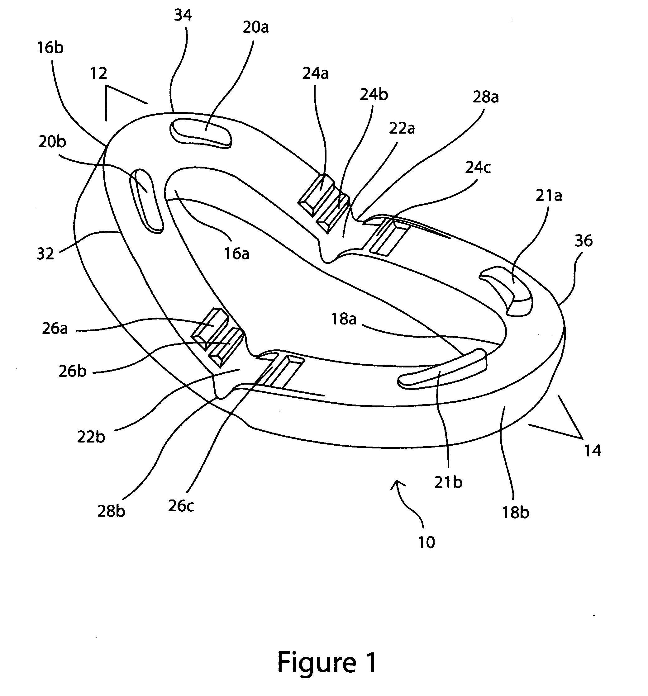
[0023]The hinge mechanism of the preferred embodiment includes a positive positioning system comprised of opposed interlocking ridges. The ridges serve to create and maintain offset between the position of the upper tray and lower tray relative to each other, therefore advancing the user's mandible. The location of the ridges, close to the hinge points, is also advantageous because the ridges continue to engage one another and therefore advance the mandible even when the jaw is almost entirely open. Further, the ridges are self-aligning and easily engage with virtually no chance of jamming.
[0024]The preferred embodiment also includes posts located near the front of the upper tray and the lower tray. These posts create an air gap that prevents the upper tray and lower tray from completely closing against one another. The preferred embodiment is also contoured and curved to comfortably fit in the mouth and on the teeth. Related to the contouring is a cleft notch on the upper front of the maxillary tray to avoid rubbing and irritation to the connective tissue (maxillary labial frenulum) on the inside of the upper lip.

Problems solved by technology

However, all such devices previously known face certain limitations.
One common limitation is that custom molding is often required to shape the device to a user's teeth or mouth.
This requires the expertise of a medical professional such as a dentist, and is therefore expensive and time-consuming.
Additionally, many devices restrict the physiological movement of the user from freely opening and closing their jaw when the device is placed in the mouth.
This is uncomfortable and unnatural for many users.
This '084 device, however, faces numerous limitations.
The simple hinge mechanism is subject to wear as the pliable material is bent over many cycles of the user's mouth opening and closing.
Fatigue of the, material, compounded by a lack of mechanical reinforcement, may allow the simple living hinge to become sloppy and loose, rendering the device unable to properly advance the mandible.
However, with this device the upper and lower members are not connected or hinged to one another.
However, with this device the upper and lower member's are not connected or hinged to one another.
However, this device requires the user to sleep with their jaw in a fixed, clenched position.
Many people find sleeping with their jaw in a fixed position to be very uncomfortable, potentially even inhibiting sleep.
Thus the post may disengage from the lower arch when the mouth is opened, causing the mandible to no longer be in an advanced position.
In addition, there's no mechanical element to prevent the device from completely closing, causing upper arch and lower arch become co-planar.
However, with this device the upper and lower members are not securely connected or hinged to one another.
The projections are made from the soft, moldable material of the rest of the device, and as such, may be difficult to engage in the apertures.
In addition, the soft material of the projections may allow movement between the upper and lower members, thus not consistently advancing the mandible.
In addition, the two members of the device may easily disengage from the teeth through the natural movement of the jaw.
This device, however, faces numerous limitations.
The simple hinge mechanism is subject to wear as the pliable material is bent over many cycles of the user's mouth opening and closing.
The mandibular advancement the device provides is created solely by the position of the hinge, and faces similar limitations to the device described in '084 (Bergersen) In addition, there's no mechanical element to prevent the device from completely closing, causing upper surface 24 and lower surface 14 to become co-planar and therefore restricting airflow through the mouth.
However, all face similar limitations as the above described inventions.
This process is costly and time-consuming, and prevents by non-skilled persons using the device straight-out-of-the-package.
Still other systems use a simple hinge that quickly wears and may no longer properly advance the mandible.
Many of these devices also restrict the user from opening his / her mouth, which many users find undesirable.

Method used


Image

  • Mandibular advancement device with positive positioning hinge
  • Mandibular advancement device with positive positioning hinge
  • Mandibular advancement device with positive positioning hinge

Examples


Embodiment Construction

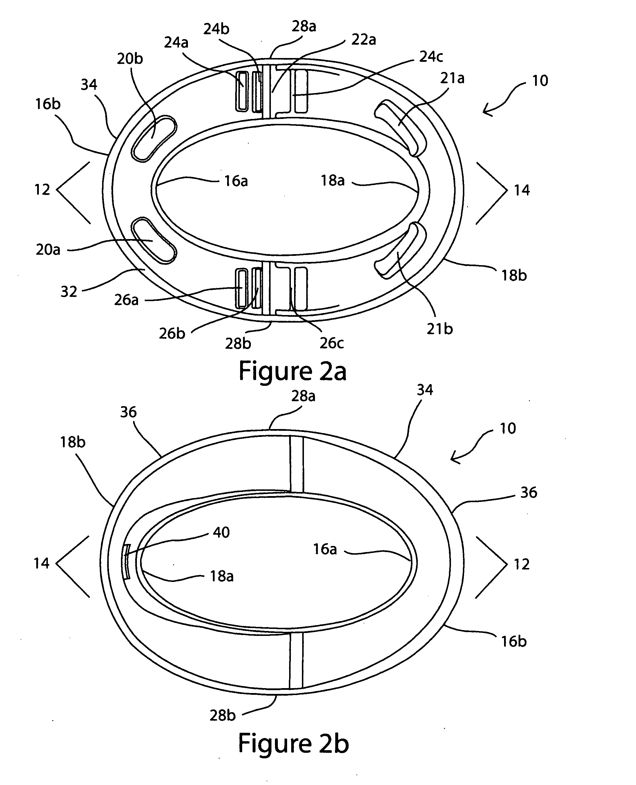
[0061]In all figures, the device is shown in the open position, when not in the user's mouth.

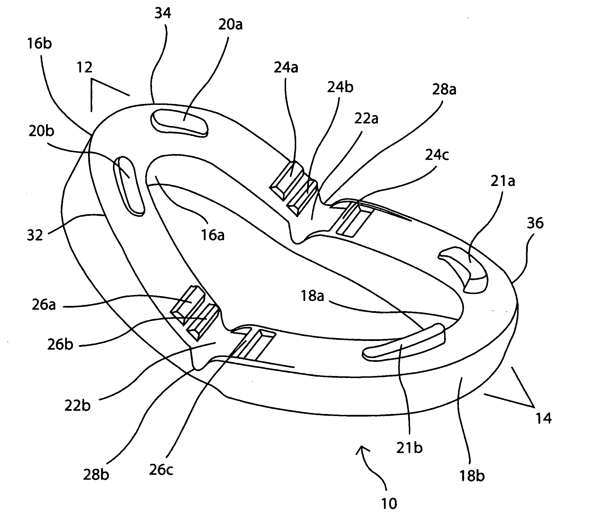
[0062]FIG. 1 is a perspective view of the preferred embodiment of the invention. As can be seen, the one-piece overall device 10 folds at overall hinge right 22a, and overall hinge left 22b. Upper maxillary tray 12 and lower mandibulary tray 14 are both u-shaped, joined together by hinges 22a and 22b. The length of the upper and lower trays are preferably designed so that the device extends back to the centers of the upper first molars when fully inserted. This allows for ample contact between the trays and the teeth to maintain device positioning, but doesn't extend too far into the mouth so as to create discomfort or promote gagging.

[0063]FIG. 1 also shows the interlocking ridges of each hinge. Forward upper interlocking ridge right 24a, aft upper interlocking ridge right 24b, lower interlocking ridge right 24c, together form the positive engagement system. The preferred embodiment uses ri...


PUM


Abstract

The invention is an oral appliance for prevention of sleeping problems including snoring, sleep apnea and bruxism. Specifically, the appliance alters the position of the user's mandible, which is known as a method for reducing the restriction of the flow of air through the pharyngeal passageway. The appliance is a one-piece device molded from a flexible polymer such as Kraton®. It includes an upper maxillary tray and a lower mandibulary tray. Both upper and lower trays include inner and outer walls which increase contact area with the teeth. The hinge mechanism of the device includes a positive positioning system comprised of opposed interlocking ridges. The ridges serve to create offset between the position of the upper tray and lower tray relative to each other, therefore advancing the user's mandible. Additional features include airflow posts to keep the mouthpiece from sealing completely, a cleft contour, and a tooth retention tab.

Description

CROSS-REFERENCE TO RELATED APPLICATION[0001]This application claims the benefit of provisional patent application No. 61 / 195,171, filed Oct. 3, 2008FEDERALLY-SPONSORED RESEARCH[0002]NoneSEQUENCE LISTING[0003]NoneBACKGROUND[0004]The present invention relates to devices for prevention of sleeping problems including snoring and sleep apnea. Specifically, the device is an oral appliance which alters the position of the user's mandible. Advancing the position of the mandibular mouth structure relative to the position maxillary mouth structure is known as a method of reducing snoring and sleep apnea by reducing the restriction of the flow of air through the pharyngeal passageway. The decrease in air flow restriction causes a reduction in the vibration of soft tissue that's a cause of snoring, as well as reducing occlusion that's a cause of sleep apnea.FIELD OF THE INVENTION[0005]It is well-established that snoring and sleep apnea are sleeping problems that effect the quality of life of ma...

Claims


Application Information

Patent Timeline
Patent Type & Authority Applications(United States)
IPC IPC(8): A61F5/56
CPCY10S602/902A61F5/566
Inventor WEBSTER, DANIELCARLBERG, LARRYLIEBERMAN, AVERY
Owner SLEEPING WELL
Learn More