Ultraviolet curing apparatus for continuous material

a curing apparatus and ultraviolet light technology, applied in the field of ultraviolet lamp systems, can solve the problems of reducing the efficiency of irradiation, limiting the diameter of the substrate being treated, and difficult threading of the substrate through the processing chamber

Inactive Publication Date: 2010-04-08
NORDSON CORP
View PDF16 Cites 15 Cited by
  • Summary
  • Abstract
  • Description
  • Claims
  • Application Information

AI Technical Summary

Benefits of technology

[0006]In an alternative embodiment, the curing system of the invention includes a processing chamber, a plasma lamp, and a microwave generator as explained above. This curing system further includes first and second reflectors for reflecting ultraviolet radiation to irradiate the substrate. The curing system also includes an ultraviolet-transmissive conduit for enclosing the substrate, positioned within the processing chamber, and comprising a first portion and a second portion movable relative to the first portion between an open position and a closed position. The open position of the ultraviolet-transmissive conduit allows for the substrate to be loaded into the conduit.

Problems solved by technology

One challenge of conventional systems is that the efficiency of irradiation decreases as the diameter of the substrate increases because the substrate moves away from the focal axis.
Therefore, the use of a completely elliptical reflector limits the diameter of the substrate being treated.
The substrate should not contact this ultraviolet-transmissive conduit, making threading the substrate through the processing chamber difficult.

Method used


Image

  • Ultraviolet curing apparatus for continuous material
  • Ultraviolet curing apparatus for continuous material
  • Ultraviolet curing apparatus for continuous material

Examples


Embodiment Construction

[0011]Although the invention will be described next in connection with certain embodiments, the invention is not limited to practice in any one specific type of ultraviolet curing system. The description of the embodiments of the invention is intended to cover all alternatives, modifications, and equivalent arrangements, as may be included within the spirit and scope of the invention, as defined by the appended claims. In particular, those skilled in the art will recognize that the components of the embodiments of the invention described herein could be arranged in multiple different ways.

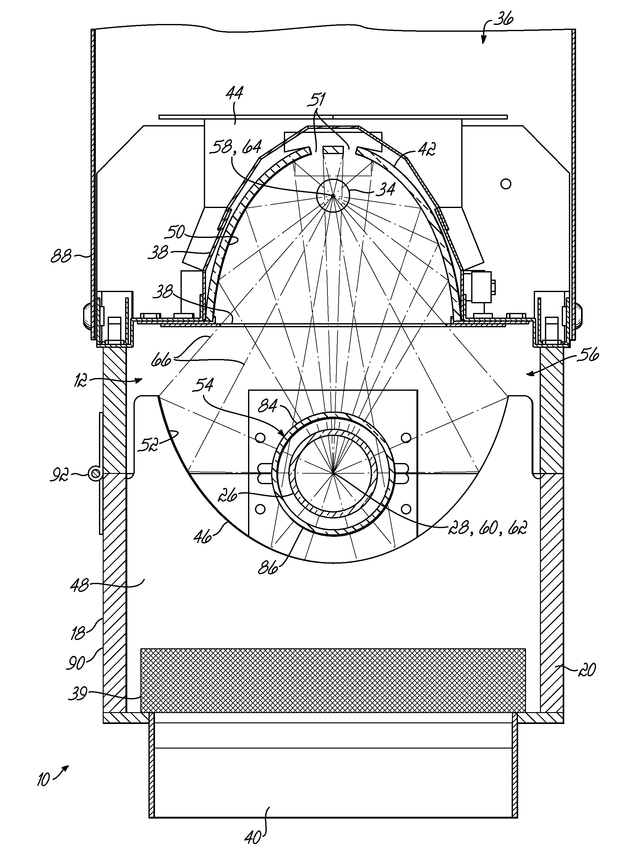
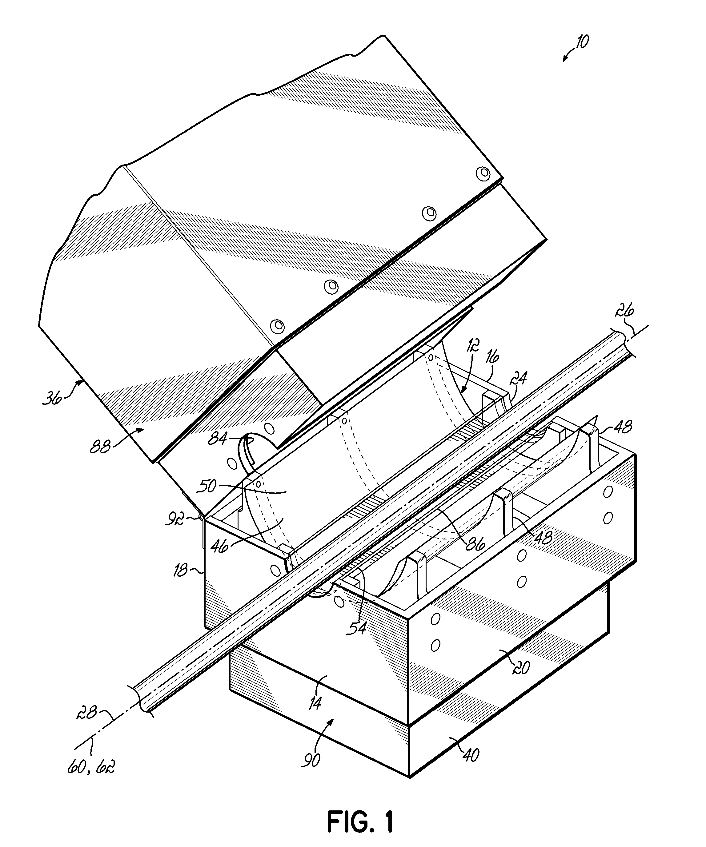
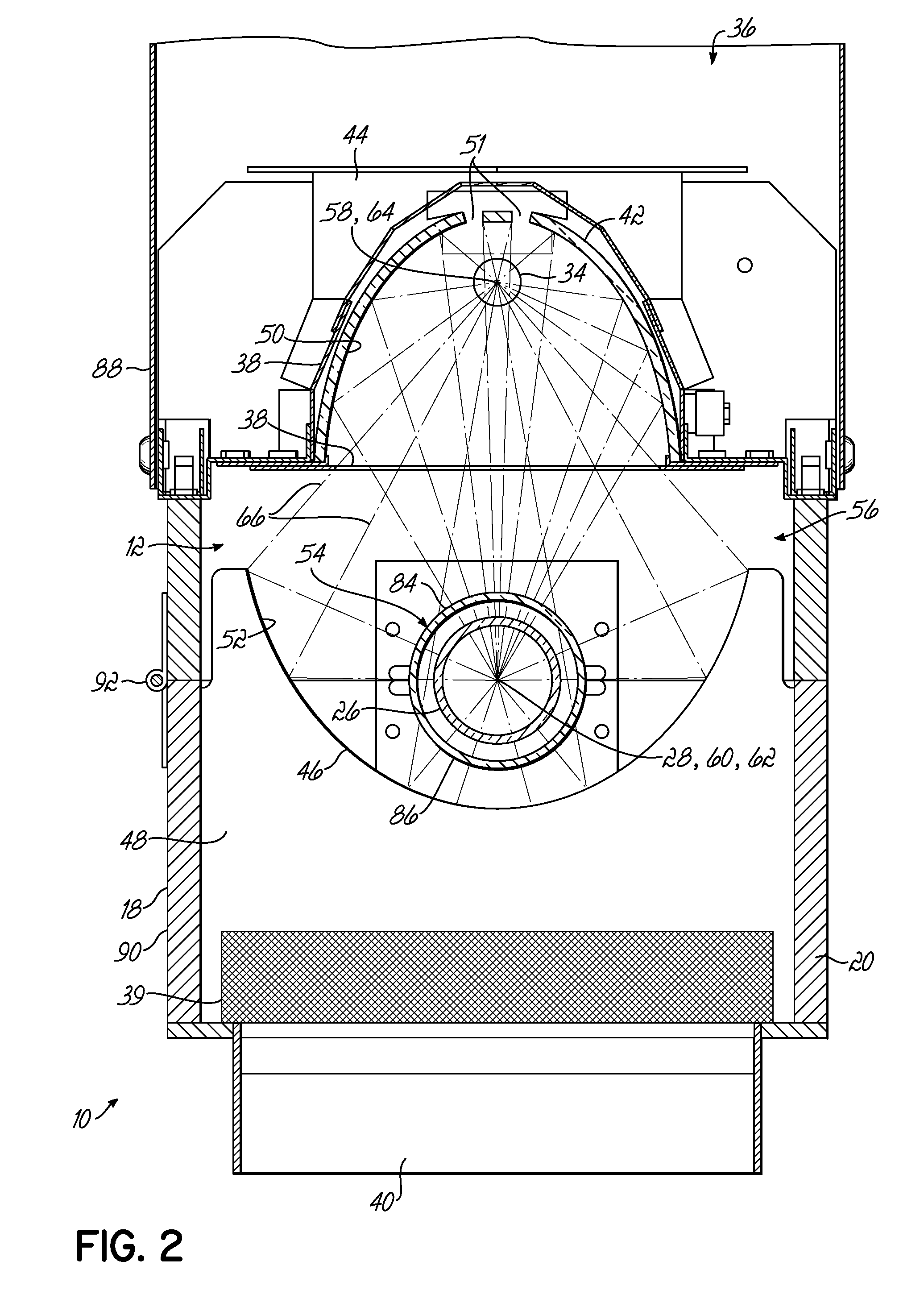
[0012]Referring now to the drawings, and specifically FIGS. 1 and 2, one embodiment of an ultraviolet radiation curing system 10 is provided. The curing system 10 includes a processing chamber 12 defined by front wall 14, back wall 16, and longitudinal side walls 18, 20. An inlet port 22 located in the front wall 14 is adapted to receive a substrate 26 for ultraviolet curing. An outlet port 24 loca...


PUM

PropertyMeasurementUnit
wavelengthsaaaaaaaaaa

Abstract

An ultraviolet radiation curing system is disclosed for treating a substrate, such as fiber optic cable or silicone tubing. The system comprises a processing chamber allowing transport of a continuous piece of substrate to be treated. As the substrate moves through the processing chamber, ultraviolet radiation from a plasma lamp activated by a microwave generator treats the surface of the substrate. The system comprises two elliptical reflectors of different sizes so that larger diameter substrates may be efficiently treated with ultraviolet radiation. The system may also comprise an ultraviolet-transmissive conduit enclosing the substrate and split into a first portion and a second portion, where the second portion is movable from the first portion to open the conduit and allow insertion or alignment of the substrate within the conduit and processing chamber.

Description

TECHNICAL FIELD[0001]The present invention relates generally to ultraviolet lamp systems, and more particularly, to microwave-excited ultraviolet lamp systems configured to irradiate a substrate with ultraviolet radiation.BACKGROUND[0002]Ultraviolet lamp systems are commonly used for heating and curing materials including adhesives, sealants, inks, and coatings, as well as optical cables and tubing. Certain ultraviolet lamp systems have electrodeless light sources and operate by exciting an electrodeless plasma lamp in a processing chamber with radiofrequency energy, such as microwave energy. In an electrodeless ultraviolet lamp system that relies upon excitation with radiofrequency energy, the plasma lamp emits a characteristic spectrum isotropically outward along its cylindrical length. Part of the emitted radiation moves directly from the plasma lamp toward a substrate located in the processing chamber. A substantial portion of the emitted radiation must be reflected before reach...

Claims


Application Information

Patent Timeline
Patent Type & Authority Applications(United States)
IPC IPC(8): G21K5/00
CPCB29C35/0888B29C35/10B29C71/04H01J65/044F26B3/28F26B13/002B29C2035/0827B05D3/029B05D3/067B05D7/20
Inventor BRASSELL, ROBERTMCGHEE, EDWARD C.SCHMITKONS, JAMES W.
Owner NORDSON CORP
Why Eureka
Try Eureka